ronawo.com 

Space-rockets with spreadable-arms invented by Roman Nawojczyk

And the SYSTEM for these space-rockets equipped with spreadable-arms.

Below are shown 50 pages with the drawings from my patent applications.

These pages are in the 40% picture resolutions with descriptions.

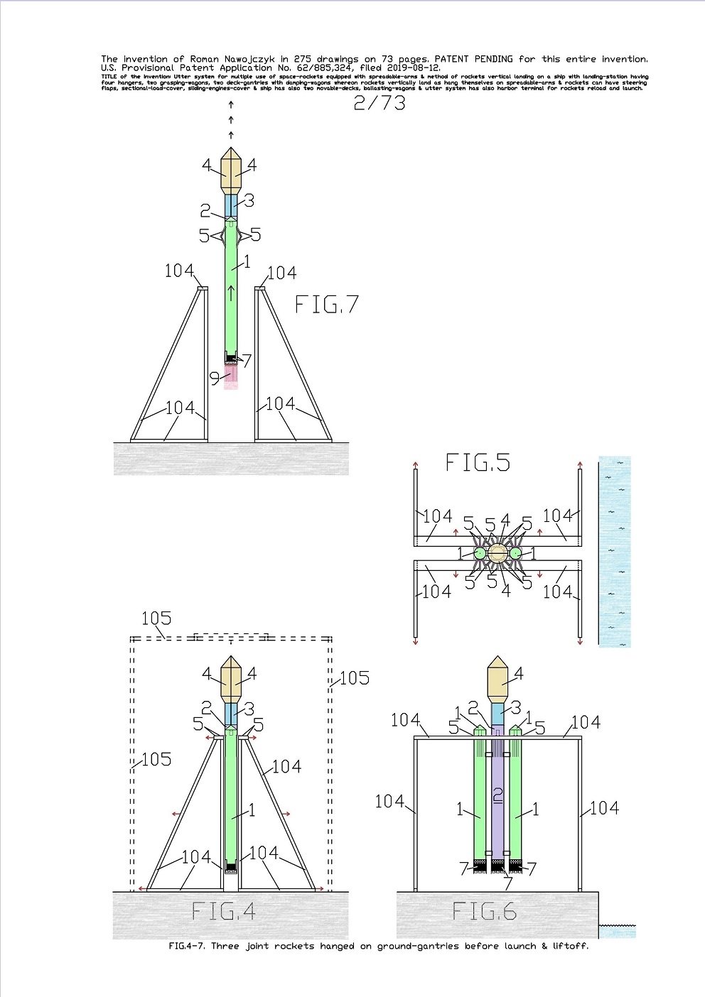
FIG.4, 5, 6 are the views which show space-rockets launch method in the system for multiple use of several space-rockets equipped with several spreadable-arms 5. Here are shown the multi-task station for three jointed space-rockets launch preparation, liftoff and later unloading from the specific sea ship 10.

It is recommended that this multi-task station would be at a sea harbor wharf so that it could be possible to reload the space rockets from any specific sea ship.

The multi-task station comprises two movable ground-gantries 104 and one movable specific ground-crane 105. Therefor currently three joined space-rockets hang on all their spreadable-arms 5 on two movable ground-gantries 104 and will liftoff this way.

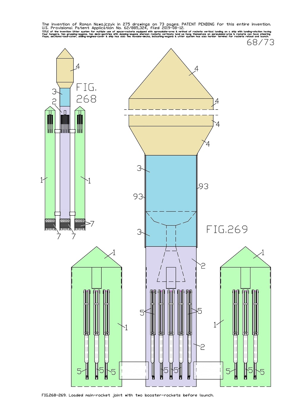
These three joined space-rockets are one main-rocket 2 which is joined on both sides with two booster-rockets 1. On the main-rocket 2 top it is mounted the assemblage which consist of the second-stage-rocket 3 with attached the sectional-load-cover 4. And on this FIG.4 is also sketched the side drawing of one movable specific ground-crane 105, because it earlier moved away. 

FIG.7 is the side view of three joined space-rockets which are awhile after the liftoff and the side view of two movable ground-gantries 104 which are spread somewhat apart on two sides.


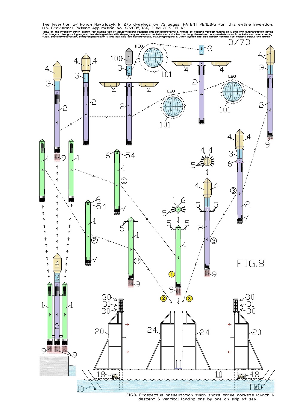
FIG.8 is a prospectus presentation which shows many crowd scenes in the system for multiple use of several space-rockets equipped with several spreadable-arms 5. The current whole presentation shows the methods of three joined space-rockets launch and entire process ascent toward the Earth's orbit, descent and vertical landing with return-load according to current invention. Therefor this FIG.8 shows for example plurality drawing statuses of three joined space-rockets with their liftoff, joined ascent, their separation, further separated ascent toward the Earth's orbit, deploy a payload, dock a return-load, and their individual descending and vertical landing aboard the specific sea ship 10 at open sea. On all rocket statuses and alongside the arrows show the directions of their traveling trajectories. These three joined space-rockets are the same as on previous FIG.4, 5, 6, 7 and further FIG.268, 269 and these are one main-rocket 2 which is joined on both sides with two booster-rockets 1.

On the main-rocket 2 top it is mounted the assemblage which consist of the second-stage-rocket 3 with attached the sectional-load-cover 4. At beginning these three rockets statuses are in two front drawings. Thereafter all rockets statuses are in the side drawings and show their travel toward the specific sea ship 10 which is in the side drawing as well.

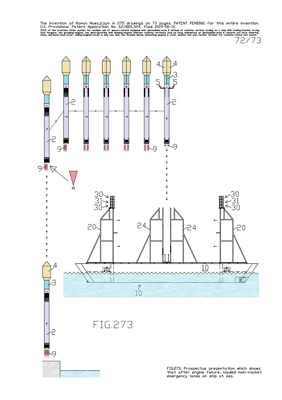
Here alongside the rocket drawing statuses are the numbers in some small circles which explain the rockets landing sequences. Descent process from the Earth's orbit individually by three space-rockets will end with vertical landing aboard the specific sea ship 10. Therefor both movable ship-gantries 20 are entirely spread apart in two directions before landing of every space-rocket as it is shown on current view. The entire prospectus presentation on FIG.8 targets presentation that is possible individual, vertical landing as many as three space-rockets equipped with spreadable-arms 5 on one specific sea ship 10 at sea.

.


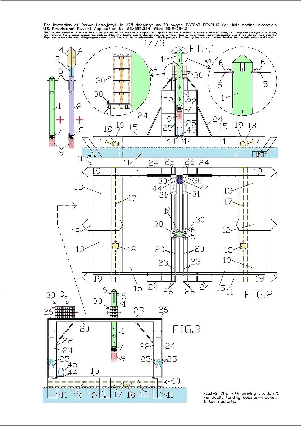
FIG.1, 2, 3 show space-rockets vertical landing method in the system for multiple use of several space-rockets equipped with several spreadable-arms 5. Here is shown the method of three space-rockets vertical landing on the specific sea ship 10 with deck-mounted landing-station having four hangers 24, two grasping-wagons 44, two movable ship-gantries 20 with several damping-wagons 30 or 31 whereon each rocket vertically lands as hangs itself on its spreadable-arms 5. On landing-station can land three space-rockets in a few minutes intervals. Two first can be quick moved on hangers and fasten. The third landed rocket remains on both movable ship-gantries and is fastened by both grasping-wagons.

The current views show just vertically landing one booster-rocket 1 with entirely lifted (spread out) all spreadable-arms 5. The FIG.1 shows additionally an enlarged fragment with the damping-wagon 30 and the second enlarged fragment of the booster-rocket 1 upper part showing the spreadable-arms 5 and a few steering flaps 6. Furthermore nearby to specific sea ship 10, current FIG.1 shows the second booster-rocket 1 and a main-rocket 2 which both have also entirely lifted (spread out) all their spreadable-arms 5. This view shows and explains that on the same specific sea ship 10 with such landing-station can still additionally vertically land these two earlier mentioned space-rockets. 


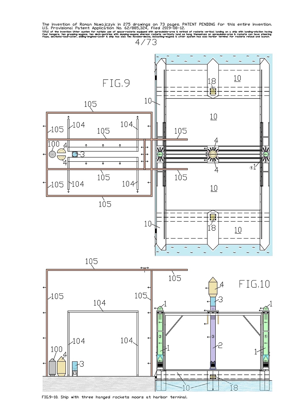
FIG.9, 10 are the views which show rockets vertical unloading method in the system for multiple use of several space-rockets equipped with several spreadable-arms 5. Here is shown the method of three space-rockets vertical unloading from the specific sea ship 10 at multi-task station according to current invention. Therefor these views shows the specific sea ship 10 which just moored at multi-task station for unloading of three space-rockets which later can be launch again together or individually.

This multi-task station consists of two movable ground-gantries 104 and of one movable specific ground-crane 105. Aboard the specific sea ship 10 are hanged and still individually fastened three space-rockets.

This view targets presentation that construction of such multi-task station is very simple and very well fitted for taking delivery of the rockets from the specific sea ship 10 after hers arriving to this multi-task station.

.

.


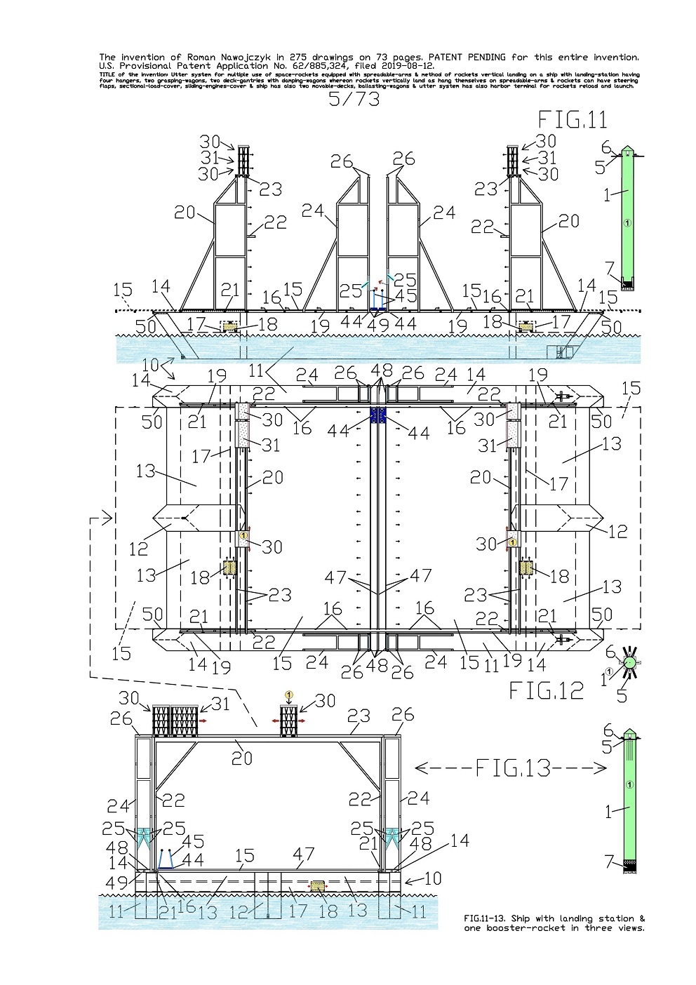
FIG.11, 12, 13 show three views of the entire specific sea ship 10 which has deck-mounted landing-station for individual, vertical landing and also for remotely-controlled fastening of three space-rockets equipped with several spreadable-arms 5. Therefor nearby the specific sea ship 10 is also one booster-rocket 1 which has entirely lifted (spread out) all spreadable-arms 5. The views show the specific sea ship 10 and the landing-station ready for landing the first booster-rocket 1. 
Both
movable ship-gantries 20 are entirely spread apart in two directions before landing of every space-rocket as it is shown on the current view. In such arrangement these both movable ship-gantries 20 are ready and await landing of every space-rocket. Therefor readiness for landing of the first booster-rocket 1 relies on entire spreading apart of these both movable ship-gantries 20 on two opposite directions of this specific sea ship 10. Furthermore readiness for landing of the first booster-rocket 1 relies also on proper setting of four damping-wagons 30 and two large damping-wagons 31 on both movable ship-gantries 20 tops. For this reason almost at centers of both movable ship-gantries 20 tops stand two damping-wagons 30 so that it could hang up on them the first landing booster-rocket 1. Whereas remaining two damping-wagons 30 and two large damping-wagons 31 stand inactively on one side of both movable ship-gantries 20 tops. 
Furthermore readiness for landing of every rocket relies also on levelling of the entire specific sea ship 10. For this reason, inside the specific sea ship 10 multi-hull are installed two ballasting-wagons 18

These two ballasting-wagons 18 are placed in two tunnels 17 which are transverse to specific sea ship 10 multi-hull. Whereat in these two tunnels 17, both ballasting-wagons 18 are currently shifted into such side-setting which maintains exactly horizontal position of the specific sea ship 10. Whereas the right places for setting all damping-wagons on both movable ship-gantries 20 tops are selected in such way which enable carrying out individual landing of three space-rockets. 
All current views show entire joined multi-hull construction of the specific sea ship 10 which consists of two long side-hulls 11 and two short central-hulls 12. All these mentioned hulls are permanently fastened with four above-water copular-hulls 13. On each long side-hull 11 surface is a main-deck 14. The specific sea ship 10 has also installed two great horizontally movable-decks 15 which can move on both main-decks 14. Both horizontally movable-decks 15 are installed directly above all joined hulls. 
Furthermore FIG.11 and FIG.12 show also possibility and range of spreading apart in two directions of these both horizontally movable-decks 15. Some arrows show the directions of spreading apart of these horizontally movable-decks 15. Currently both horizontally movable-decks 15 are pushed to each other and touch on themselves in the specific sea ship 10 center. 
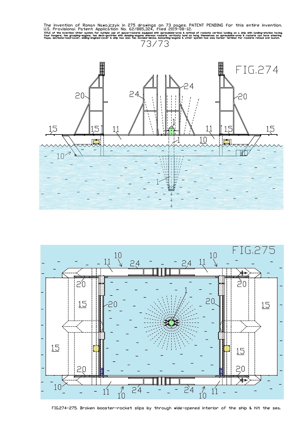
Furthermore both horizontally movable-decks 15 are sketched with the dashed lines after their entire spreading apart in two directions. After spreading apart in two directions both horizontally movable-decks 15, inside the specific sea ship 10 multi-hull will arise a giant open interior where-into is only sea surface. The 
specific sea ship 10 with entirely spread apart in two directions both horizontally movable-decks 15 is also shown on FIG.274, 275. 


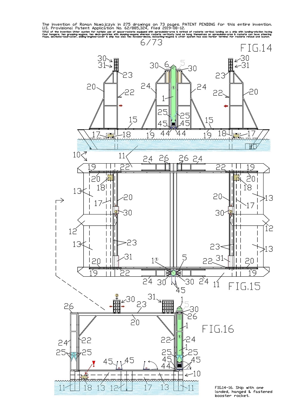
FIG.14, 15, 16 show three views of the entire specific sea ship 10 which has deck-mounted landing-station for individual, vertical landing and also for remotely-controlled fastening of three space-rockets equipped with several spreadable-arms 5. 
These views show this specific sea ship 10 and the landing-station ready for landing the second booster-rocket 1 because on her earlier already landed the first booster-rocket 1. Therefor here the specific sea ship 10 is with one booster-rocket 1 which hangs on two hangers 24 and is already fastened at bottom by means of four rotating-wedges 25.

This booster-rocket 1 earlier landed and furthermore it is still fastened also at bottom by means of four rotating-poles 45 which reach from two grasping-wagons 44. 
Both grasping-wagons 44 are currently under this booster-rocket 1. 
Readiness for landing of every rocket relies also on levelling of the entire specific sea ship 10. For this reason, inside the specific sea ship 10 multi-hull are installed two ballasting-wagons 18. These two ballasting-wagons 18 are placed in two tunnels 17 which are transverse to specific sea ship 10 multi-hull. Whereat in two tunnels 17, both ballasting-wagons 18 are currently shifted almost entirely on the specific sea ship 10 one side because on opposite side is hanged the booster-rocket 1. It causes that the entire specific sea ship 10 has equal level.


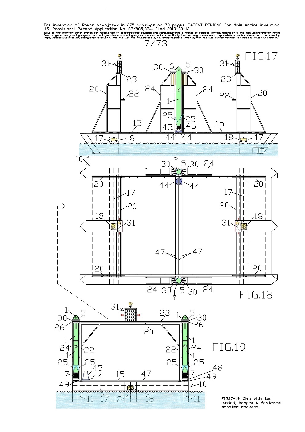
FIG.17, 18, 19 show three views of the entire specific sea ship 10 which has deck-mounted landing-station for individual, vertical landing and also for remotely-controlled fastening of three space-rockets equipped with several spreadable-arms 5.
These views show this specific sea ship 10 and the landing-station ready for landing the third space-rocket because earlier already landed two booster-rockets 1. Lately landed the second booster-rocket 1 which hung up itself by means of its all spreadable-arms 5 on two damping-wagons 30 which were earlier suitably placed on both 
movable ship-gantries 20 tops as on previous FIG.14, 15, 16. 
Current views show the specific sea ship 10 with two booster-rockets 1 whereas each one hangs on two hangers 24 and each one is fastened at bottom by means of four rotating-wedges 25.

These two rockets earlier landed and currently the views show this specific sea ship 10 and the landing-station ready for landing the third space-rocket which will be the main-rocket 2. 
Readiness for landing of the main-rocket 2 relies as previously on entire spreading apart of both 
movable ship-gantries 20 on two opposite directions of this specific sea ship 10. Furthermore this readiness also relies on setting two large damping-wagons 31 at centers of two movable ship-gantries 20 tops as on the current views. These two large damping-wagons 31 stand now in centers of two movable ship-gantries 20 tops so that it could hang up on them the main-rocket 2. Furthermore readiness for landing of every rocket relies also on levelling of the entire specific sea ship 10. For this reason, inside the specific sea ship 10 multi-hull are installed two ballasting-wagons 18. These two ballasting-wagons 18 are placed in two tunnels 17 which are transverse to specific sea ship 10 multi-hull. Whereat in two tunnels 17, both ballasting-wagons 18 are currently shifted to specific sea ship 10 center and it currently maintains exactly horizontal position of this specific sea ship 10.


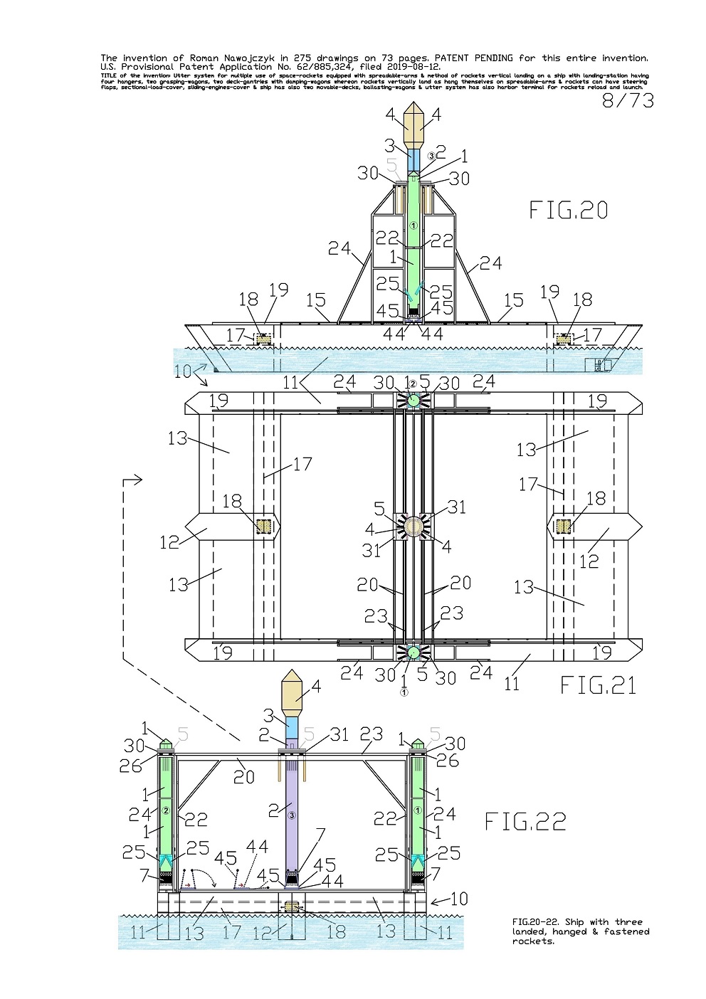
FIG.20, 21, 22 show three views of the entire specific sea ship 10 which has deck-mounted landing-station for individual, vertical landing and also for fastening of three space-rockets equipped with several spreadable-arms 5. 
These views show the specific sea ship 10 with three individually hanged and fastened space-rockets and which are ready for transporting over sea for unloading at multi-task station. On this specific sea ship 10 earlier landed two booster-rockets 1 and furthermore as the third landed the main-rocket 2. Here this main-rocket 2 hangs at centers of two 
movable ship-gantries 20 and is fastened at bottom by means of four rotating-poles 45 which reach from two grasping-wagons 44. As the last, landed just this main-rocket 2 which hung up itself by means of its all ten spreadable-arms 5 on two large damping-wagons 31 which were earlier placed at centers of two movable ship-gantries 20 tops as on previous FIG.17, 18, 19.

After the main-rocket 2 hanging itself, both large damping-wagons 31 became entirely compressed and which is well visible on FIG.20 and 22. 
Whereat in two tunnels 17, both ballasting-wagons 18 are now shifted to specific sea ship 10 center and it maintains exactly horizontal position of this specific sea ship 10. 
As it was earlier mentioned the current views show the specific sea ship 10 in fullness loaded with three space-rockets and ready for seafaring for unloading at multi-task station.

Presented here the specific sea ship 10 with landing-station having strong fastening of the rockets enables sea-transportation even at stormy sea. Whereat in two tunnels 17, both ballasting-wagons 18 serve also for automatic, continuous, quick and precise ballasting of this specific sea ship 10 during seafaring.

.


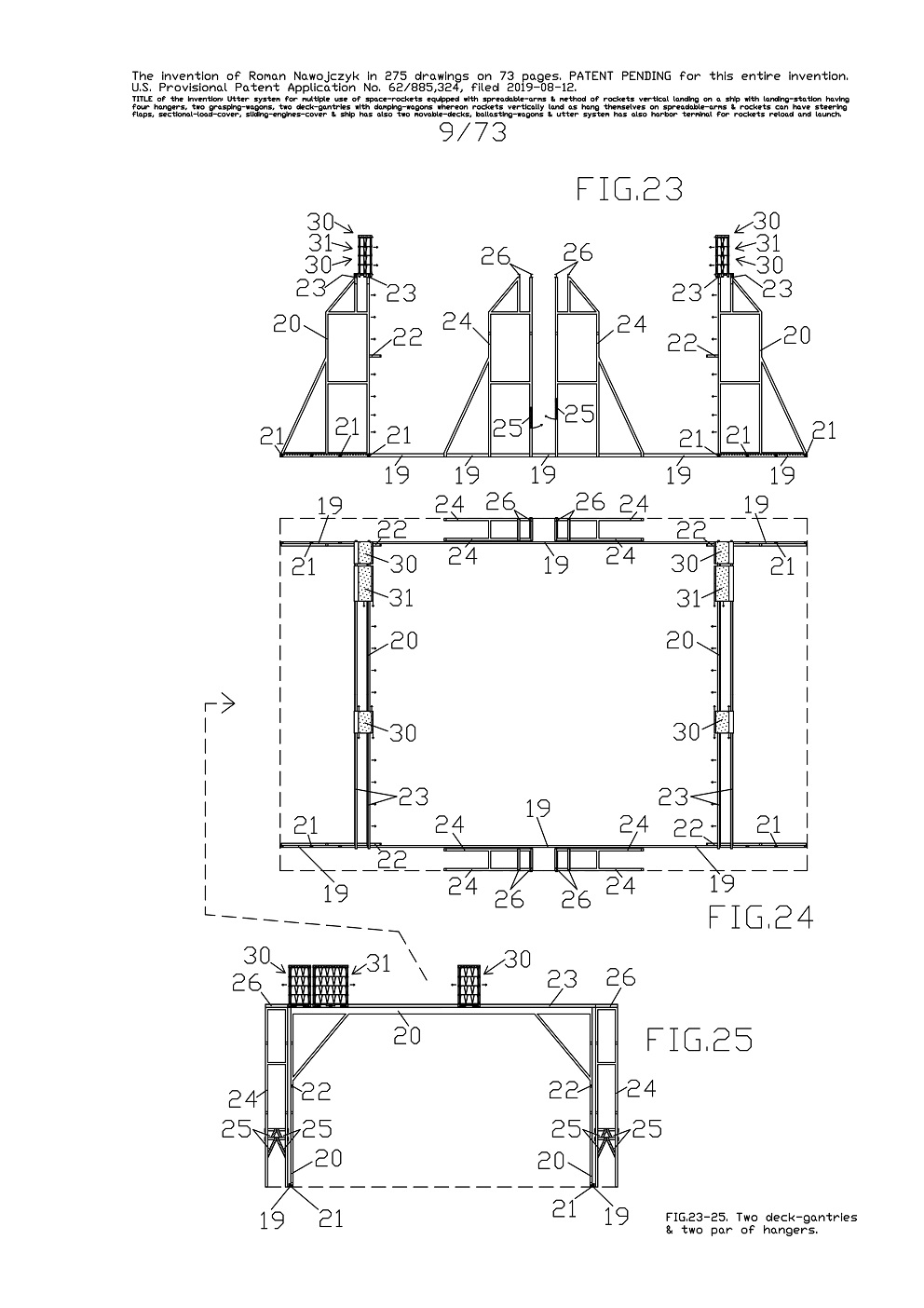
FIG.23, 24, 25 show three views of the alone entire landing-station for individual, vertical landing of three space-rockets.
This landing-station is in the same arrangement like aboard the specific sea ship 10 however the current views are without the grasping-wagons 44. This landing-station for individual, vertical landing of three space-rockets consist of two pairs of hangers 24 and of two 
movable ship-gantries 20. Two rockets after landing can be quick moved from two movable ship-gantries 20 to four hangers 24. Therefor in the landing-station are mounted four hangers 24 this way that one par of hangers 24 is mounted on each side of the specific sea ship 10. 
The hangers 24 in construction reminds immovable towers.

Each hanger 24 has two rotating-wedges 25 which serve for remotely-controlled fastenings of one space-rocket. One par of hangers 24 serve for hanging one space-rocket and fastening it by means of four rotating-wedges 25. On each hanger 24 top are two upper-short-rails 26. Whereas on each movable ship-gantry 20 top are two upper-long-rails 23. Therefor on both movable ship-gantries 20 tops are together four upper-long-rails 23 whereon stand four damping-wagons 30 and two large damping-wagons 31. Both movable ship-gantries 20 can separably roll along the entire specific sea ship 10 on two deck-rails 19. For rolling both movable ship-gantries 20 use their own plurality wheels 21. 
Furthermore in both 
movable ship-gantries 20, each one has two bumpers 22 distinctly protruding forwards. Currently both movable ship-gantries 20 are entirely spread apart in two directions, the same as on earlier FIG.11-19 and next FIG.270-272.


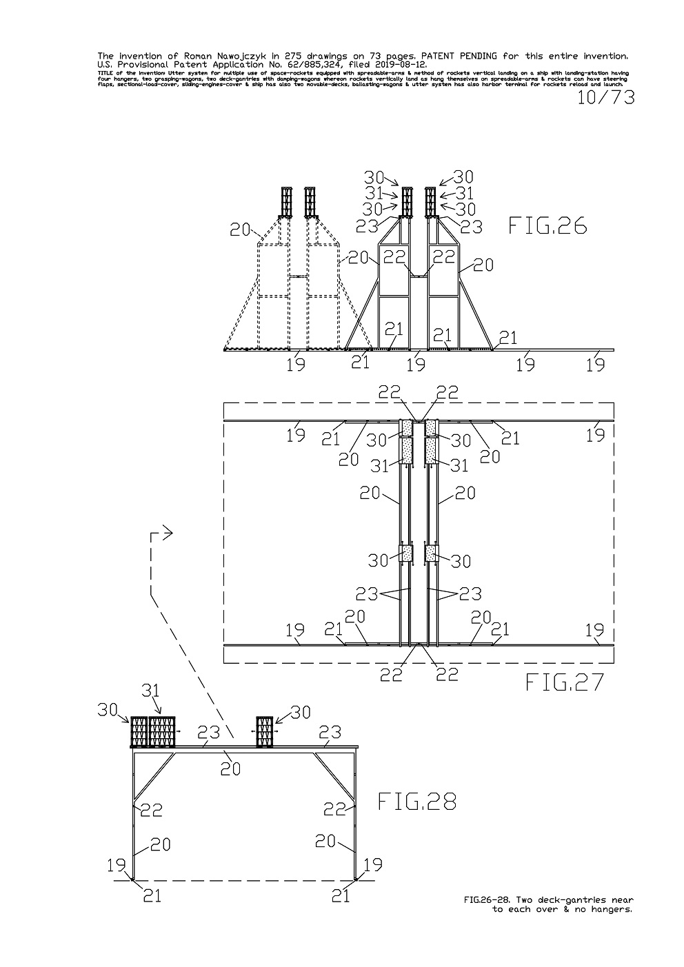
FIG.26, 27, 28 show three views of two whole movable ship-gantries 20 by themselves which are in the same arrangement like aboard the specific sea ship 10 and the same as on FIG.1, 2, 3 and 11, 12, 13.
Currently both 
movable ship-gantries 20 approached to each other because earlier rolled on their own plurality wheels 21 on two deck-rails 19. After approaching to each other, both movable ship-gantries 20 touch on themselves with the bumpers 22. Both movable ship-gantries 20 can precisely and separably roll on the deck-rails 19 along the entire specific sea ship 10. These deck-rails 19 are common for both movable ship-gantries 20 and it causes that both movable ship-gantries 20 can roll on their whole-length.

Therefor each movable ship-gantry 20 can roll until direction of the opposite movable ship-gantry 20, if necessary during landing of some space-rocket. It causes that each space-rocket can land almost on entire length of the specific sea ship 10. While on all drawings there are shown only landings examples in the ship center.
On FIG.26 shows it the sketch of both 
movable ship-gantries 20 which rolled together maximally to left side on the deck-rails 19.
On both 
movable ship-gantries 20 tops are together four upper-long-rails 23 whereon stand four damping-wagons 30 and two large damping-wagons 31.

.


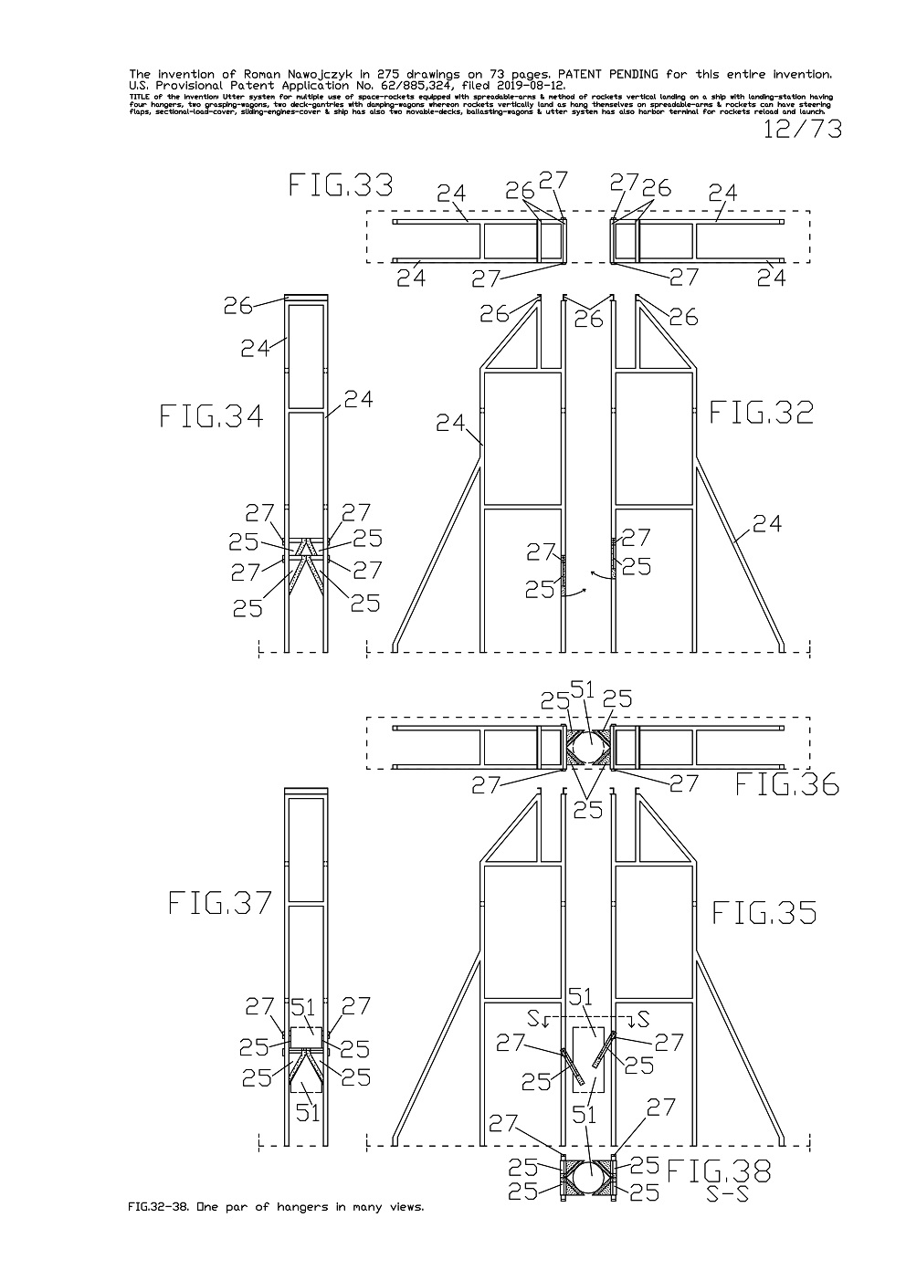
FIG.32, 33, 34 show three enlarged views of one pair of hangers 24 wherein each has two rotating-wedges 25 lowered and with the arrows showing their rotating directions. Each rotating-wedge 25 has its own rotary-actuator 27.Whereas FIG.32 is the side view, FIG.33 is the top view, FIG.34 is the front view.
The hangers 24 are permanently fastened onto main deck 14 of the specific sea ship 10 and therefor are immobile. On each hanger 24 top there are two upper-short-rails 26 and whereon can roll in one damping-wagon 30.

FIG.35, 36, 37 show the enlarged views of one pair of hangers 24 with the rocket-fuselage 51 fragment which is fastened by means of four rotating-wedges 25. These four rotating-wedges 25 are rotated in such way that they all together tighten up this rocket-fuselage 51 fragment.Whereas FIG.35 is the side view, FIG.36 is the top view, FIG.37 is the front view.
FIG.38 is the top view of the horizontal sectional view according to S-S line on FIG.35. Here, from above are visible four rotating-wedges 25 tightening the rocket-fuselage 51 fragment. The enlarged views of the rotating-wedges 25 are shown on FIG.45-54.


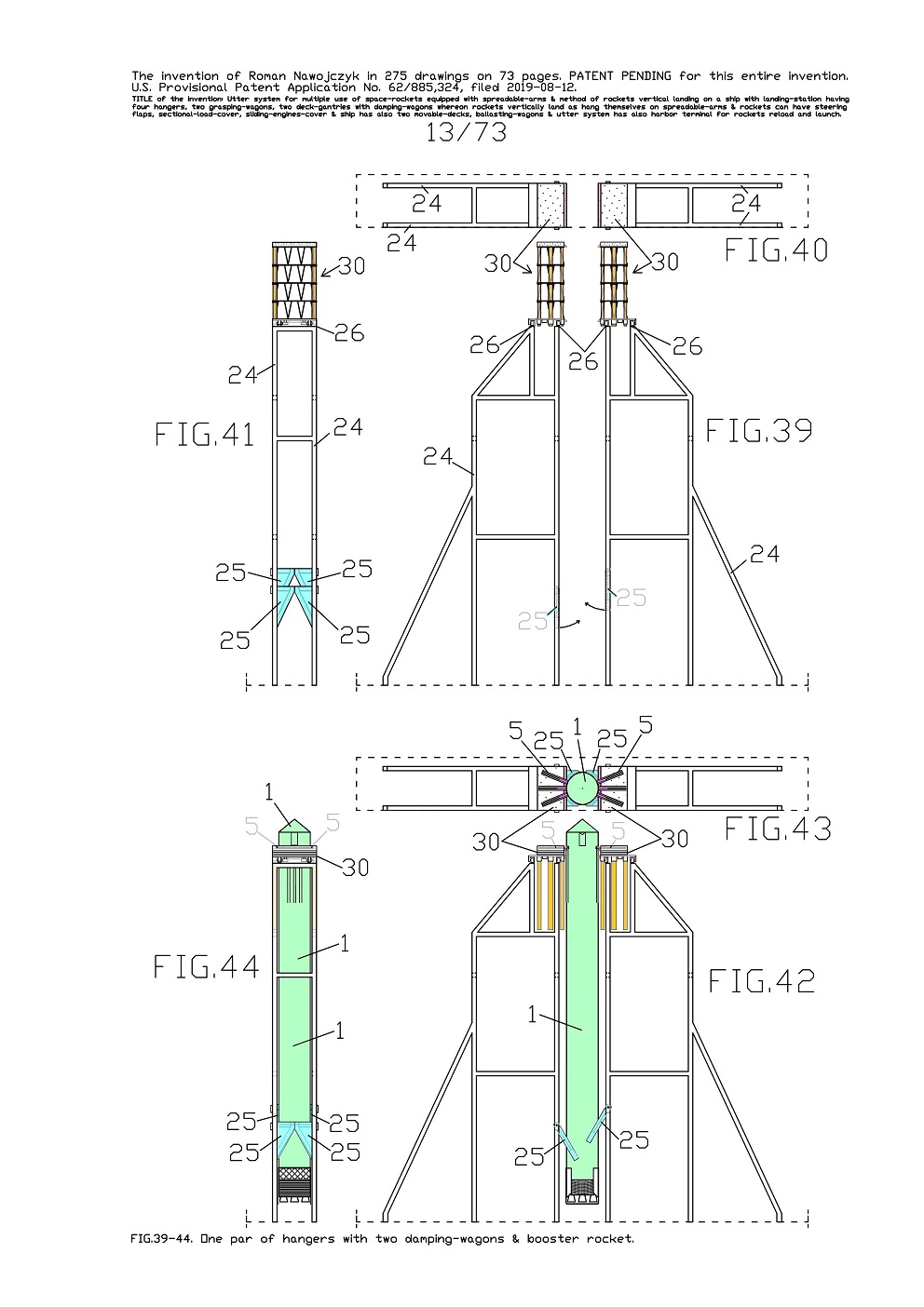
FIG.39, 40, 41 show three enlarged views of one pair of hangers 24 whereon tops in the upper-short-rails 26 stand two damping-wagons 30. These two damping-wagons 30 are not compressed because they are not loaded with any rocket. 
FIG.42, 43, 44 show three enlarged views of one pair of hangers 24 with hanged and fastened one booster-rocket 1. This booster-rocket 1 all six spreadable-arms 5 lay on two damping-wagons 30 which are entirely compressed by weight of this rocket.

Simultaneously the booster-rocket 1 in its bottom is fastened by means of four rotating-wedges 25. 
Aboard the specific sea ship 10 fastening of every rocket bottom is absolutely necessary for seagoing even at small sea-waving. Without fastening of the rocket bottoms, these rockets would swing during a little rolling the specific sea ship 10. 
Presented here the fastening solutions of the space-rockets bottoms are very strong and these enable the sea-transportation of these rockets even at hefty sea-waving.


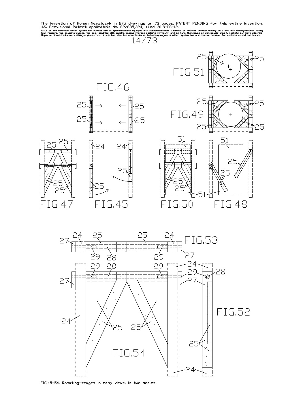
FIG.45, 46, 47 show three enlarged views of the rotating-wedges 25 with some hanger 24 fragments sketches which are performed with the dashed lines. All four rotating-wedges 25 are completely lowered and with the arrows showing their rotating directions. And FIG.45 is the side view, FIG.46 is the top view, FIG.47 is the front view. The opposite hangers 24 have the rotating-wedges 25 mounted on varied heights so that they would not hook each over.
FIG.48, 49, 50 show three enlarged views of four rotating-wedges 25 which are rotated in such way that they all together tighten up the rocket-fuselage 51 fragment. Whereas FIG.48 is the side view, FIG.49 is the top view, FIG.50 is the front view. Each rotating-wedge 25 has flexible coatings in some suitable places and they are marked with some dots on the views. These flexible coatings are intended for direct contacts with the space-rockets.

FIG.51 is the top view and shows for example the rocket bottom that is moved away from correct location. If some rocket accidentally hung up itself aslant then all rotating-wedges 25 will enable pushing this rocket to as best location as its possible in order to fasten this rocket. It shows this FIG.51 and here two upper rotating-wedges 25 are pushing this rocket bottom.
FIG.52, 53, 54 show three a lot enlarged views of two rotating-wedges 25 which are completely lowered. Whereas FIG.52 is the side view, FIG.53 is the top view, FIG.54 is the front view. Two rotating-wedges 25 which are installed on one hanger 24, have a common support-axle 28. Each rotating-wedge 25 has its own rotating-axle 29 with its own rotary-actuator 27. Thus each rotating-wedge 25 can rotate apart other rotating-wedges 25.

.


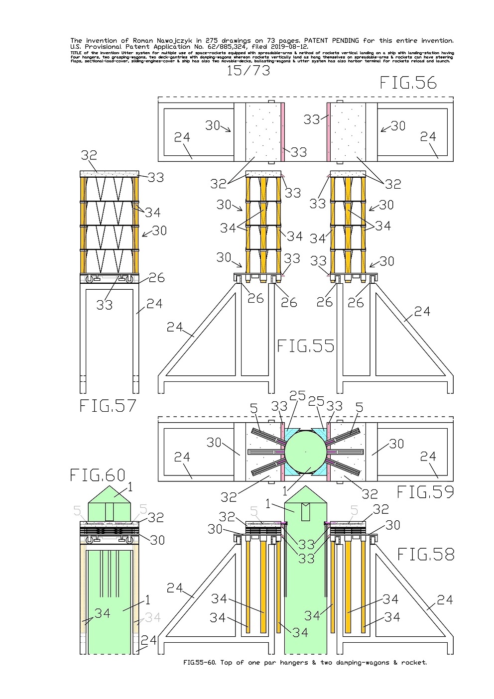
FIG.55, 56, 57 show three a lot enlarged views of one pair of hangers 24 upper part in the same statuses as were earlier shown on FIG.39, 40, 41. On the hangers 24 tops and on the upper-short-rails 26 stand two damping-wagons 30. These two damping-wagons 30 are not compressed because they are not loaded with any load. On both damping-wagons 30 tops are situated thick flexible-layers 32 which are marked with the dots on the views. Furthermore there are also permanently fastened flexible wedge-shaped-fenders 33 in the uppermost and bottom part of each damping-wagon 30. There are also visible all leading-shafts 34 in not compressed both damping-wagons 30. 

FIG.58, 59, 60 show three a lot enlarged views of one pair of hangers 24 upper part in the same statuses as were earlier shown on FIG.42, 43, 44. Here on one pair of hangers 24 is hanged one booster-rocket 1. All six spreadable-arms 5 of this one booster-rocket 1 lay on two damping-wagons 30 which are in fullness compressed by weight of this rocket. All six spreadable-arms 5 penetrated and couched on two thick flexible-layers 32 on both damping-wagons 30 tops.

Furthermore there are also visible four flexible wedge-shaped-fenders 33 whereon is leaned against the booster-rocket 1 frame. 
It is also visible that compressed both damping-wagons 30 lowered their all leading-shafts 34 and which do not hook and collide with any components of the hangers 24 and of the 
movable ship-gantries 20. 
On FIG.59 from above are also visible four rotating-wedges 25 which fastened the booster-rocket 1 in its bottom. 
Consequently, constructions of the entire hangers 24 and of the
movable ship-gantries 20 are entirely adapted with constructions and function of all damping-wagons 30 and large damping-wagons 31. 
Therewith the compressed damping-wagons 30 are able to move over from two 
movable ship-gantries 20 onto two hangers 24. 
All current views also show that the damping-wagons 30 and the large damping-wagons 31 have damping high range during hanging on them the space-rockets equipped with several spreadable-arms 5. This damping high range of all damping-wagons influence very beneficially on durability of all fastenings which upbear the spreadable-arms 5 onto rocket frame. 

.


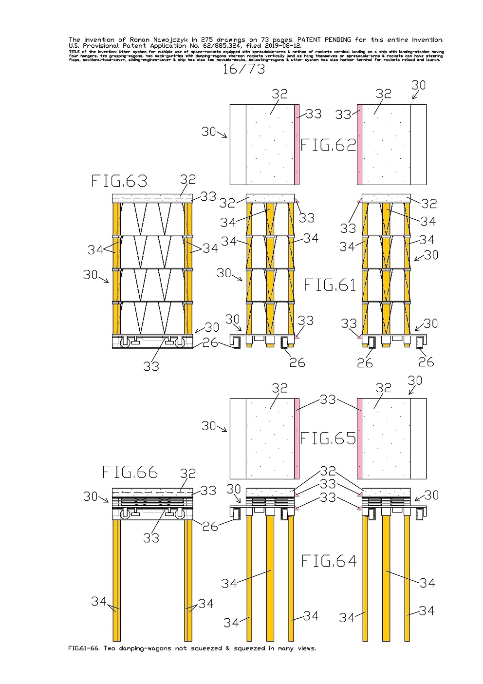
FIG.61, 62, 63 show three a lot enlarged views of two damping-wagons 30 which are not compressed and they stand on the upper-short-rails 26 which are on tops of one pair of hangers 24. These two damping-wagons 30 are in the same setting as on previous FIG.55, 56, 57. Here is visible construction of two damping-wagons 30 and their interrelationship because for one rocket hanging itself there are necessary suchlike two damping-wagons 30.

FIG.64, 65, 66 show three a lot enlarged views of two damping-wagons 30 and which for example are compressed and stand on the upper-short-rails 26 which are on tops of one pair of hangers 24. These two damping-wagons 30 are in the same setting as on previous FIG.58, 59, 60. Here is also visible that compressed both damping-wagons 30 lowered their all leading-shafts 34. Here, except of the upper-short-rails 26 there are not other fragments of the hangers 24.


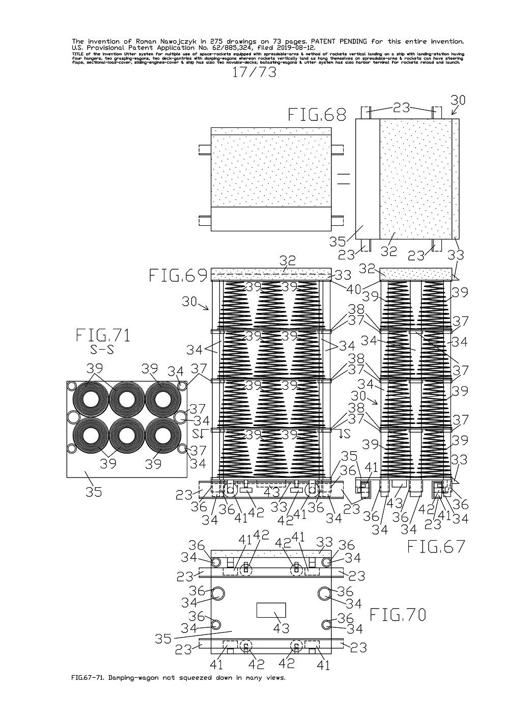
FIG.67, 68, 69, 70, 71 show several a lot enlarged views and the horizontal sectional view and a bottom projection of one entire damping-wagon 30 which is not compressed and in different manner than previously, stands on two upper-long-rails 23 which are on one movable ship-gantry 20 top. Whereas FIG.67 is the side view, FIG.68 is the top view in two equal views which are rotated 90 degrees in relation to each other so that they cohere with the below views. And FIG.69 is the front view, FIG.70 is the bottom projection. And FIG.71 is the top view of the horizontal sectional view according to S-S line on FIG.69. There are visible all sub-assemblies and construction of one damping-wagon 30.
Each damping-wagon 30 has one main-plate 35 with on both sides permanently fastened six high-leading-tubes 36. Under the main-plate 35 are installed four driving-wheels 41, four leading-wheels 42 and a battery 43. In all driving-wheels 41 are installed electric motors powered of the battery 43. Above the main-plate 35 are permanently fastened the bottoms of six conic-springs 39 in vertical setting. Whereat these six conic-springs 39 tops are permanently fastened to being situated above them a middle-plate 38.
Presented here, one damping-wagon 30 has three middle-plates 38 with conic-springs 39 in the very same settings and fastenings. Whereat tops of six uppermost conic-springs 39 are permanently fastened to being situated above them a top-plate 40.

This top-plate 40 has on both sides permanently fastened six leading-shafts 34 which are spaced out suitably to being situated under them the low-leading-tubes 37 in all middle-plates 38 and all high-leading-tubes 36 in the main-plate 35.
Above the top-plate 40 is permanently fastened the thick flexible-layer 32 which is marked with the dots on the views. On this flexible-layer 32 will couch all six spreadable-arms 5 which are applied in the booster-rocket 1. Furthermore to top-plate 40 and to flexible-layer 32 on one side is permanently fastened the flexible wedge-shaped-fender 33. The same flexible wedge-shaped-fender 33 is also permanently fastened to main-plate 35 one side.
As result of such solution, one damping-wagon 30 has four layers of the conic-springs 39 which can be in fullness compressed and which create damping high range.
The damping-wagons 30 are designed for rolling by from the upper-long-rails 23 on both 
movable ship-gantries 20 onto upper-short-rails 26 on the hangers 24. It is possible because the upper-short-rails 26 on the hangers 24 fit to upper-long-rails 23 on both movable ship-gantries 20 while, these both movable ship-gantries 20 stand at ship 10 center. It means the damping-wagons 30 can be situated on the movable ship-gantries 20 or on the hangers 24. All upper-long-rails 23 and all upper-short-rails 26 are in C-profiles and thus all damping-wagons cannot fall out off them.


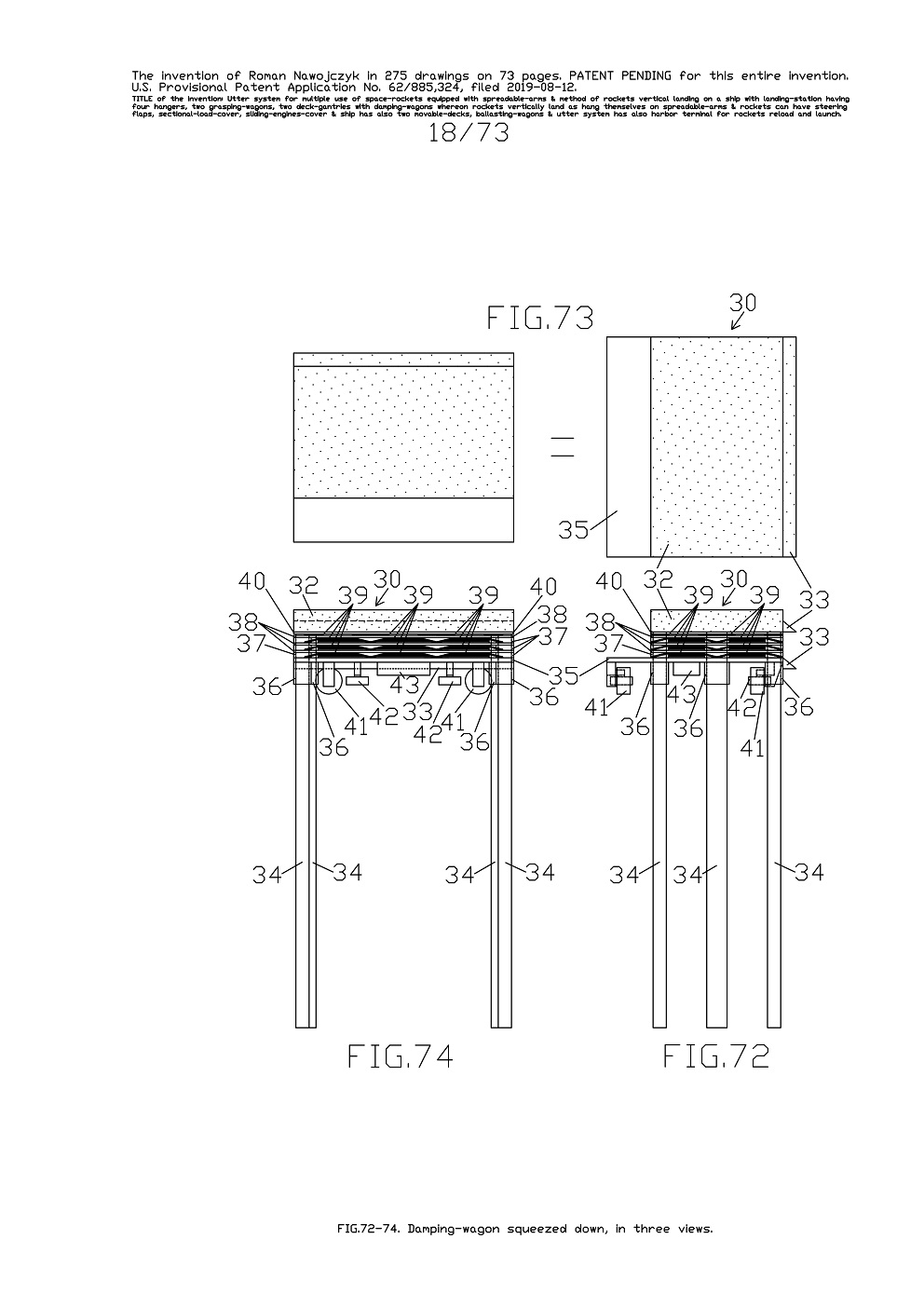
FIG.72, 73, 74 show three a lot enlarged views of one entire damping-wagon 30 and which for example is compressed and does not stand on any rails. Whereas FIG.72 is the side view. And FIG.73 is the top view of one damping-wagon 30 in two equal views which are rotated 90 degrees in relation to each other so that they cohere with the below views. And FIG.74 is the front view. Here is visible that all conic-springs 39 are entirely compressed. Whereat all conic-springs 39 in the highest layer are perfectly entirely compressed.

Whereat all conic-springs 39 in the lower three layers are compressed to low-leading-tubes 37 height. Here is also visible that all leading-shafts 34 over-passed all low-leading-tubes 37 and all high-leading-tubes 36. As result all leading-shafts 34 are hanging by themselves down under the damping-wagon 30. This solution of the leading-shafts 34 which are fitted with all leading tubes creates damping high range and simultaneously maintains unshaken and stable top surface of all damping-wagons during compressing by rocket.


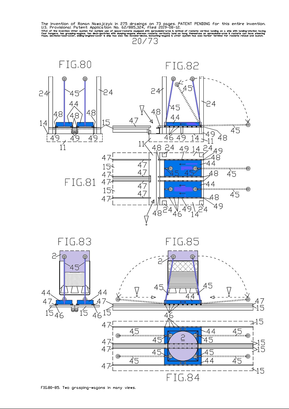
FIG.80, 81, 82 show three views of two grasping-wagons 44 wherein each with two rotating-poles 45. These two grasping-wagons 44 stand on four short-transverse-rails 48. The current views show the rotating-poles 45 lifted to setting similar as during holding the space-rocket. Whereat the sketches of two right rotating-poles 45 together with the arrows show their total possible rotation range. 
The short-transverse-rails 48 are based on several pillars 49 which are situated between two hangers 24 and visible on a lot views. All pillars 49 stand on two main-decks 14 which are on two long side-hulls 11. Both grasping-wagons 44 have plurality of the wheels 46 in order to they could roll by long intervals which are between the short-transverse-rails 48 and the long-transverse-rails 47. These intervals are best visible on FIG.81, 82 and are indicated with the large exclamation marks.

Both grasping-wagons 44 wherein each has two rotating-poles 45 with spherical ends which have flexible coatings. These flexible coatings are intended for direct contacts with the space-rockets. 
FIG.83, 84, 85 show three views of two grasping-wagons 44 which stand on four long-transverse-rails 47. These both grasping-wagons 44 by means of four rotating-poles 45 tighten one main-rocket 2 bottom in the same way as on earlier FIG.20-22 though on those FIGs. a lot of the components are veiled by other members. 
Furthermore on current views, the sketches of all inclined down rotating-poles 45 together with the arrows show their required inclination down, so that the entire grasping-wagons 44 could move underneath this hanged main-rocket 2. It is best visible on FIG.85 and somewhat on FIG.83 and it is indicated with two large exclamatory signs. Furthermore on FIG.81, 82, 84, 85 the arrows on the grasping-wagons 44 show their possible moving directions.


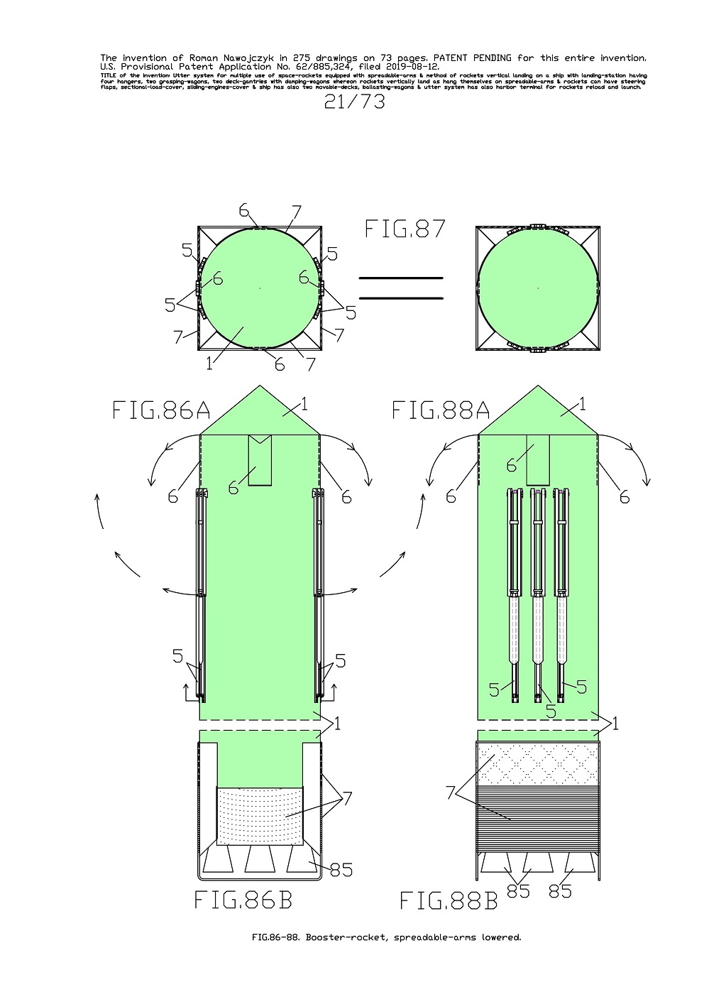
FIG.86A, B and FIG.87 and FIG.88A, B show three views of one booster-rocket 1 upper and bottom parts which has six spreadable-arms 5, four steering flaps 6 and one sliding-engines-cover 7. 
Whereas FIG.86A is the side view of one booster-rocket 1 upper part. And FIG.86B is the side view of one booster-rocket 1 bottom part. And FIG.87 is the top view in two equal views which are rotated 90 degrees in relation to each other so that they cohere with the below views. And FIG.88A, B are the front views.
On current views the sliding-engines-cover 7 is entirely lifted and it uncovered all nozzles 85 of this rocket main engines.

Here all spreadable-arms 5 are entirely lowered and consequently are alongside the rocket frame. 
Whereat all four flaps 6 are vertically set and are entirely inside the rocket frame. 
On FIG.86A, B and FIG.88A ,B the external arrows show the spreading directions of the spreadable-arms 5 and deflection of the flaps 6. 
The quantity of the spreadable-arms 5 mounted on each space-rocket depends on its weight.
Therefor currently in one booster-rocket 1 are mounted six spreadable-arms. These spreadable-arms 5 are suitably spaced out in each rocket frame so that they all could completely spread out on two sides.


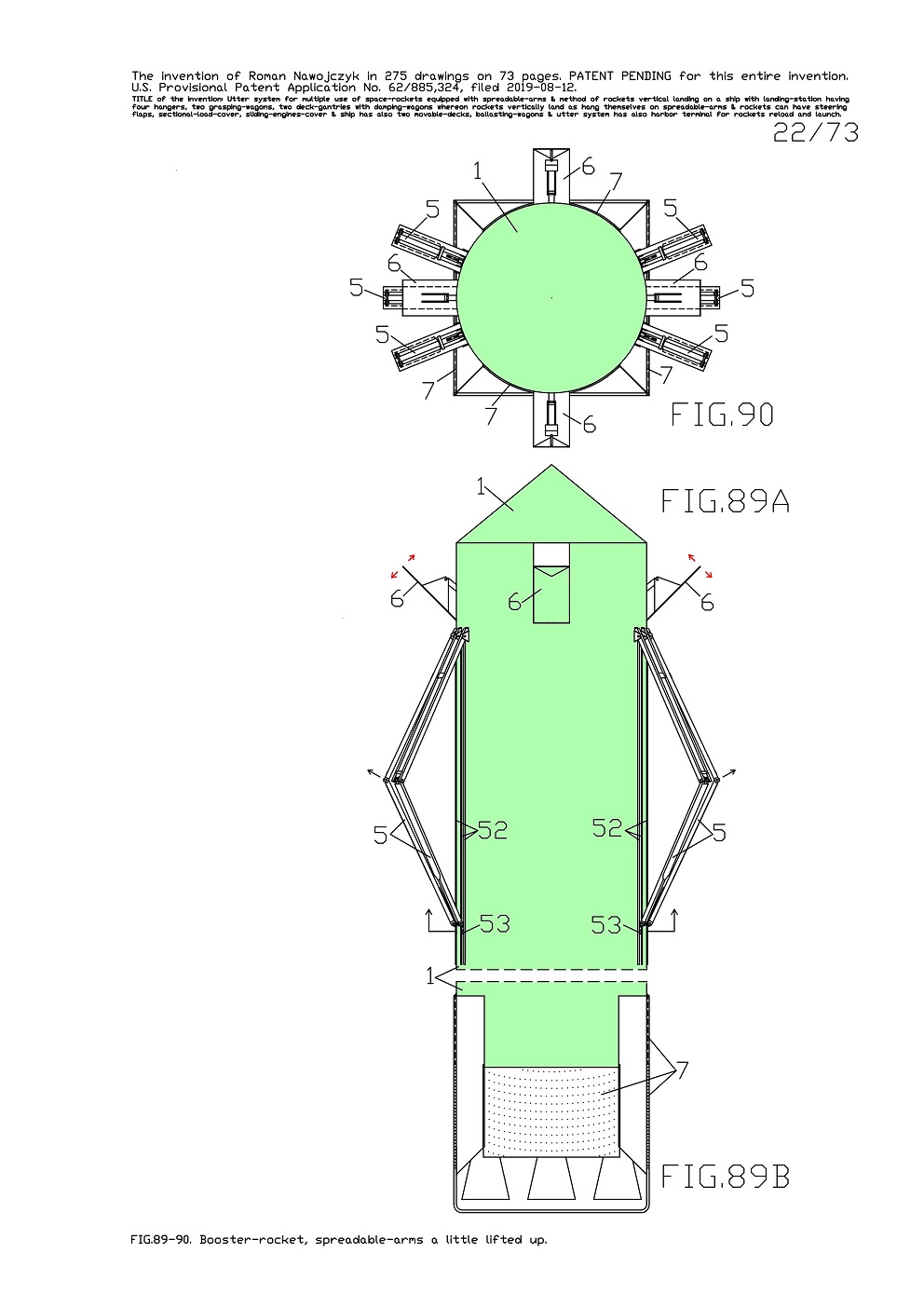
FIG.89A, B and FIG.90 show two views of one booster-rocket 1 upper and bottom parts which has a little lifted all six spreadable-arms 5 and consequently they a little protrude outside the rocket frame. Whereat all four flaps 6 are a lot deflected out and consequently protrude outside the rocket frame. Whereat the sliding-engines-cover 7 is entirely lifted.

Whereas FIG.89A is the side view of one booster-rocket 1 upper part. And FIG.89B is the side view of one booster-rocket 1 bottom part. And FIG.90 is the top view of FIG.89A, B in the same arrangement and situation. On FIG.89A, B the arrows show the spreading directions of the spreadable-arms 5 and deflection of the flaps 6. On FIG.89A, B, on the rocket frame are clearly visible several corner-beams 52 which lead sliders 53 of the spreadable-arms 5.


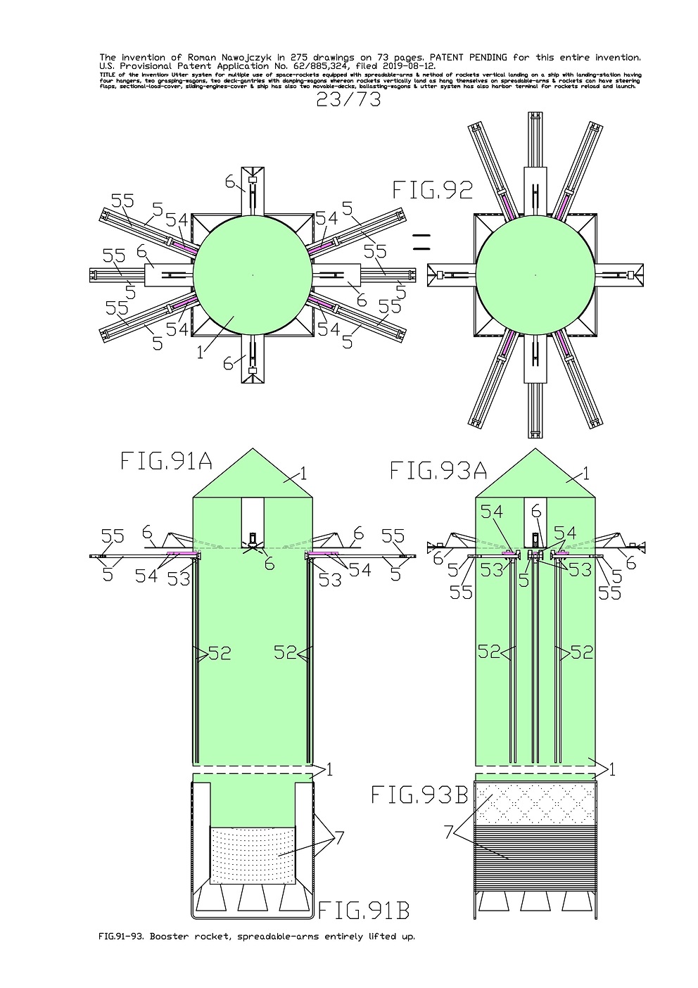
FIG.91A, B and FIG.92 and FIG.93A, B show three views of one booster-rocket 1 upper and bottom parts. This booster-rocket 1 has entirely lifted all six spreadable-arms 5 and consequently they are completely spread out on two sides. And therefor these spreadable-arms 5 are transverse the rocket frame. 
Furthermore
currently all blocking-bars 54 are entirely slid outside the rocket frame and it entirely blocked all middle-beams 55 in all spreadable-arms 5. Whereat all four flaps 6 are entirely deflected out and consequently are horizontally and transverse the rocket frame.

Whereat the sliding-engines-cover 7 is entirely lifted and it uncovered all nozzles of the main engines. 
Whereas FIG.91A is the side view of one booster-rocket 1 upper part. And FIG.91B is the side view of one booster-rocket 1 bottom part. 
And FIG.92 is the top view in two equal views which are rotated 90 degrees in relation to each other so that they cohere with the below views. 
And FIG.93A is the front view of one booster-rocket 1 upper part. And FIG.93B is the front view of one booster-rocket 1 bottom part. On FIG.91A and FIG.93A, on the rocket frame are also clearly visible several corner-beams 52 which lead the sliders 53 of the spreadable-arms 5.


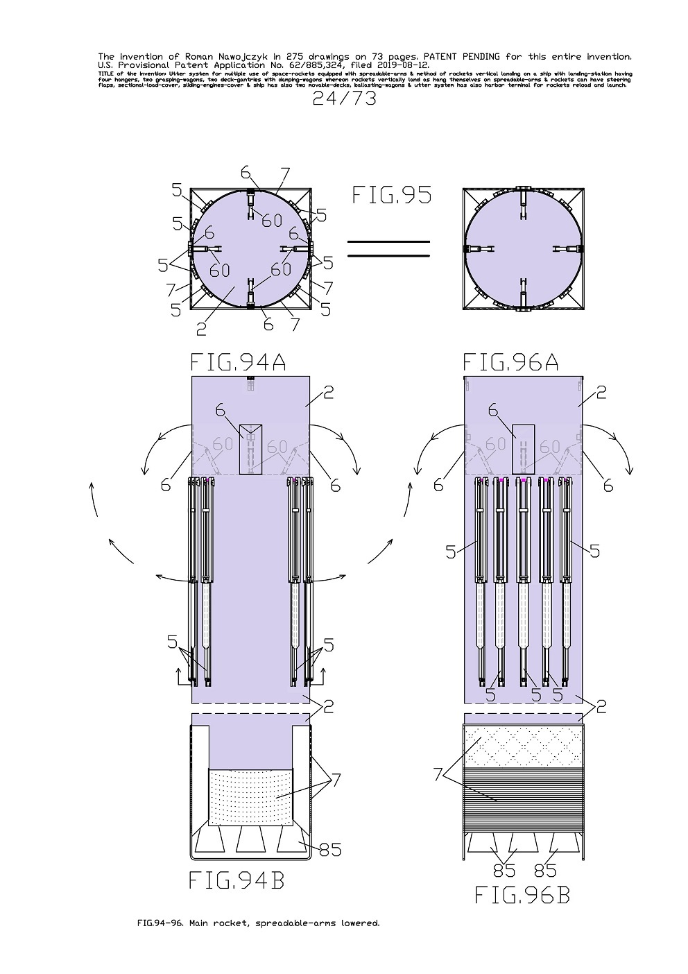
FIG.94A, B and FIG.95 and FIG.96A, B show three views of one main-rocket 2 upper and bottom parts which has ten spreadable-arms 5, four steering flaps 6 and one sliding-engines-cover 7. Currently all spreadable-arms 5 are entirely lowered and consequently are alongside the rocket frame. The quantity of spreadable-arms 5 mounted on each space-rocket depends on its weight. Therefor currently in one main-rocket 2 are mounted ten spreadable-arms 5. These spreadable-arms 5 are suitably spaced out in each rocket frame so that they all could completely spread out on two sides. Whereat all four flaps 6 are vertically set and entirely inside the rocket frame.

Whereat the sliding-engines-cover 7 is entirely lifted and it uncovered all nozzles of the main engines. 
Whereas FIG.94A, B are the side views. And FIG.95 is the top view in two equal views which are rotated 90 degrees in relation to each other so that they cohere with the below views. And FIG.96A, B are the front views. On FIG.94A, B and FIG.96A, B the arrows show the spreading directions of the spreadable-arms 5 and deflection of the flaps 6. On FIG.95 are visible some linear-actuators 60 which steer deflections of the flaps 6. Whereat on FIG.94A, B and FIG.96A, B, these linear-actuators 60 are sketched with the dashed lines because they are situated inside the rocket frame.


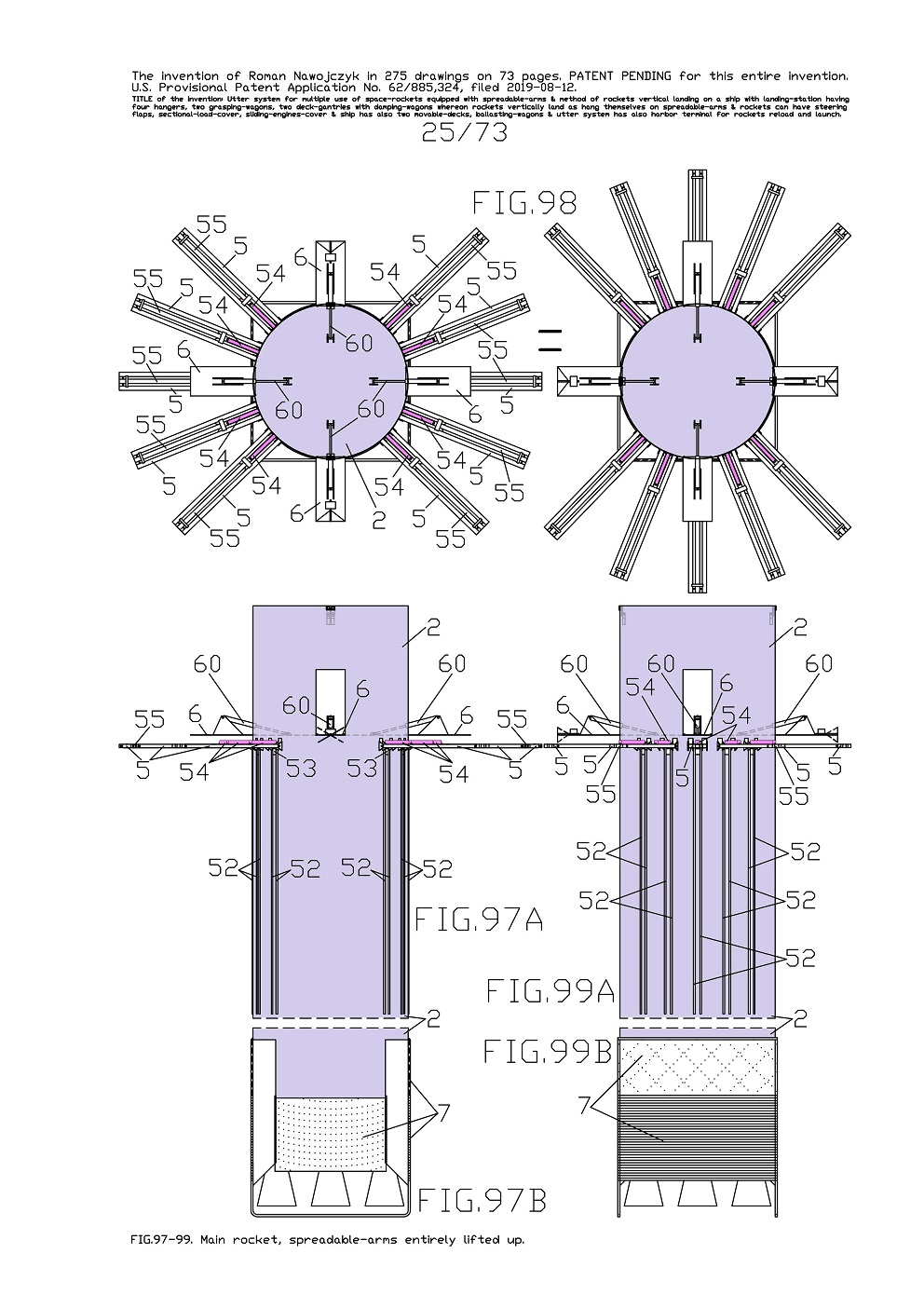
FIG.97A, B and FIG.98 and FIG.99A, B show three views of one main-rocket 2 upper and bottom parts which has entirely lifted all ten spreadable-arms 5 and consequently they are completely spread out on two sides. And therefor these spreadable-arms 5 are transverse the rocket frame. Furthermore currently all blocking-bars 54 are entirely slid outside the rocket frame and it entirely blocked all middle-beams 55 in all spreadable-arms 5. Whereat all four flaps 6 are entirely deflected out and consequently are horizontally and transverse the rocket frame.

On all views are visible the linear-actuators 60 which steer deflections of the flaps 6. 
Whereat
the sliding-engines-cover 7 is entirely lifted
Whereas FIG.97A, B is the side view. And FIG.98 is the top view in two equal views which are rotated 90 degrees in relation to each other so that they cohere with the below views. And FIG.99A, B is the front view. 
On FIG.97A, B are clearly visible several whole corner-beams 52 on this rocket frame. These corner-beams 52 lead the sliders 53 of the spreadable-arms 5.


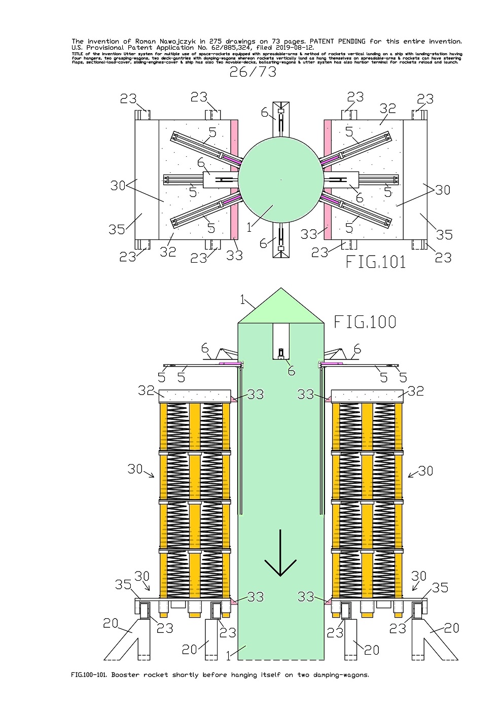
FIG.100, 101 show two views of one booster-rocket 1 upper part and of two movable ship-gantries 20 upper part whereon tops stand two damping-wagons 30 and which are not compressed
These views show just vertically landing the booster-rocket 1 which in a moment will hang itself on two damping-wagons 30. This rocket has entirely lifted (spread out) all six spreadable-arms 5 which do not lay yet on the flexible-layers 32 on the damping-wagons 30. Whereat four flaps 6 are entirely deflected outside the rocket frame.

On FIG.101 are visible four flexible wedge-shaped-fenders 33 whereon the rocket frame is already leaned against in despite of, this rocket does not yet hang up itself on both damping-wagons 30. On this FIG.101 is not shown below situated the sliding-engines-cover 7. 
The current views target showing fitting way of both damping-wagons 30 with six spreadable-arms 5 in one booster-rocket 1. The current views are a little similar to FIG.42, 43 and FIG.58, 59 and there one booster-rocket 1 already hangs on compressed two damping-wagons 30 but which stand on two hangers 24.


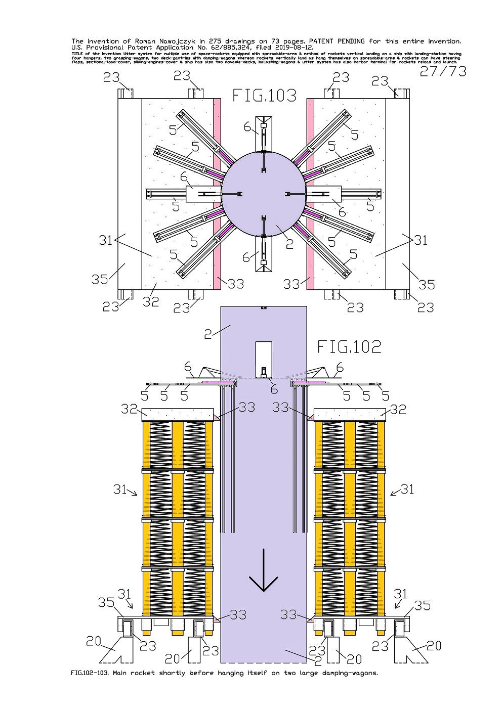
FIG.102, 103 show two views of one main-rocket 2 upper part and of two movable ship-gantries 20 upper part whereon tops stand two large damping-wagons 31 and which are not compressed. These views show just vertically landing main-rocket 2 which in a moment will hang up itself on two large damping-wagons 31. This rocket has entirely lifted (spread out) all ten spreadable-arms 5 which do not lay yet on the flexible-layers 32 on these large damping-wagons 31. 

Whereat four flaps 6 are entirely deflected outside the rocket frame. On FIG.103 are visible four flexible wedge-shaped-fenders 33 whereon is already leaned against this rocket frame in despite of this rocket does not hang up yet on both large damping-wagons 31. On this FIG.103 is not shown below situated the sliding-engines-cover 7. The current views target showing fitting way of both large damping-wagons 31 with ten spreadable-arms 5 in one main-rocket 2. 


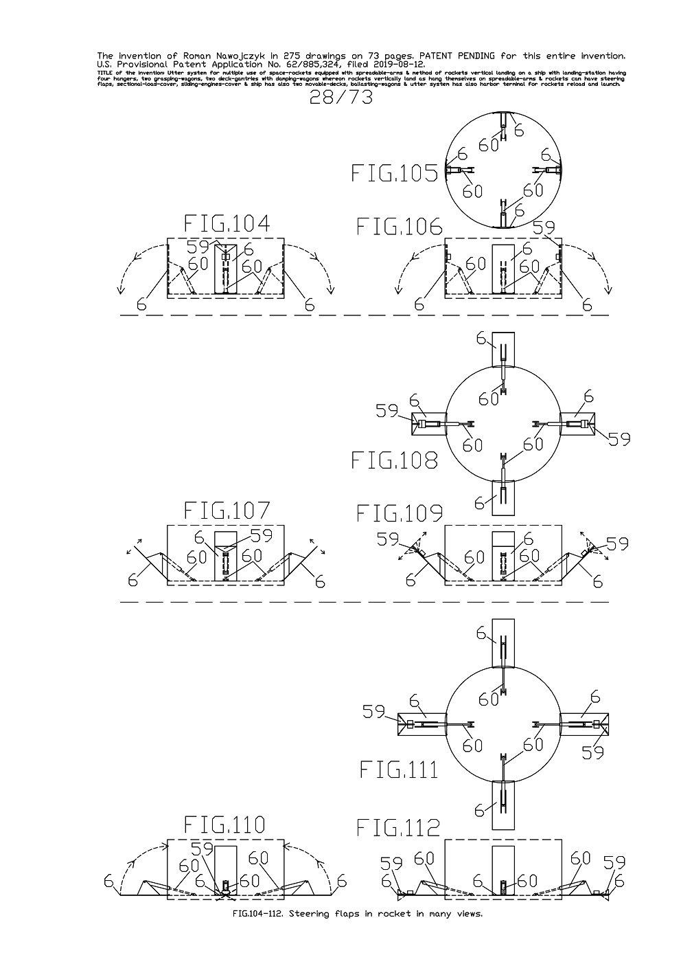
FIG.104, 105, 106 show three views of four steering flaps 6 installed in the main-rocket 2 upper part. Currently all four flaps 6 are vertically set and are entirely inside the rocket frame. They are set this way during the rocket ascent toward space. Here the arrows show the deflection out directions of the flaps 6. Whereas FIG.104 is the side view, FIG.105 is the top view, FIG.106 is the front view. All four flaps 6 are in large sizes so that they could steer the rockets even at low speeds of their descent in the Earth's atmosphere. Each space-rocket has installed four steering flaps 6. Two opposite flaps 6 have additionally installed some torsional-triangles 59 which serve for precise steering of entire rocket axial torsion, needed before landing on two movable ship-gantries 20.
FIG.107, 108, 109 show three views of four steering flaps 6 in the main-rocket 2 upper part. Currently all four flaps 6 are a lot deflected outside ergo mainly for steering the rocket at average speed of its descent in the Earth's atmosphere as on FIG.215-216. Whereas FIG.107 is the side view, FIG.108 is the top view, FIG.109 is the front view. On current views the arrows show possible the deflection out directions of the flaps 6. Furthermore on FIG.109 two torsional-triangles 59 are sketched in a few settings varies twisted.

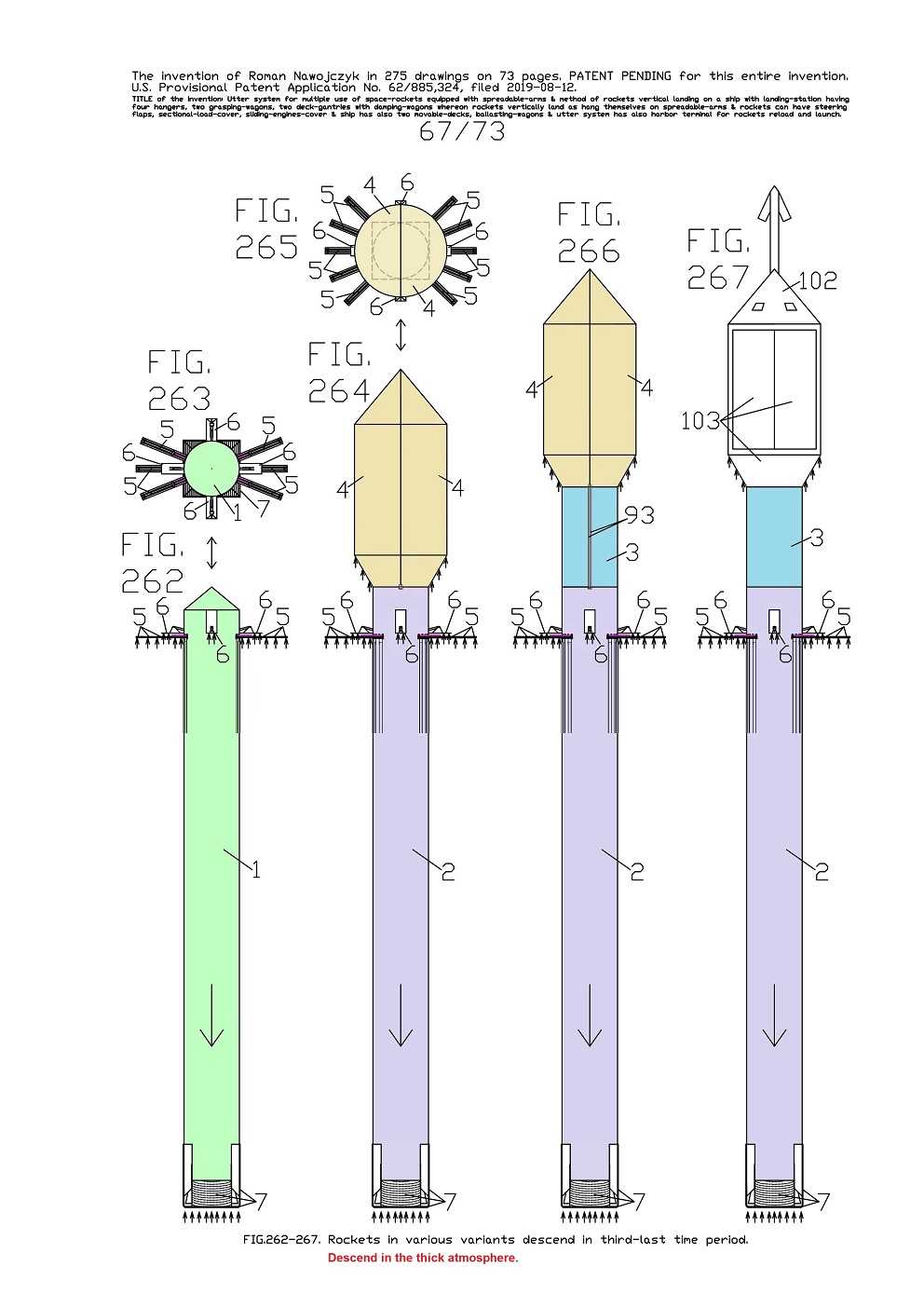
FIG.110, 111, 112 show three views of four steering flaps 6 in the main-rocket 2 upper part. Currently all four flaps 6 are entirely deflected outside ergo mainly for aerodynamic braking and steering the rocket at low speed of its descent in the Earth's atmosphere as on FIG.262-267. And FIG.110 is the side view, FIG.111 is the top view, FIG.112 is the front view.
On current views the arrows show the return direction of flaps 6. Moreover here the torsional-triangles 59 are also sketched in a few settings varied twisted. The views on FIG.104-112 show also four deflection mechanisms of the flaps 6. Each such deflection mechanism consists of one linear-actuator 60 and of two ample-brackets 57. The linear-actuators 60 steer deflections of the flaps 6 while, the ample-brackets 57 are subsidiary. These ample-brackets 57 are not marked on the current views but only on next FIG.113-118. On current top views the deflection mechanisms are in fullness visible. While the side views and the front views contain both the views and the sketches of the deflection mechanisms.

.

.


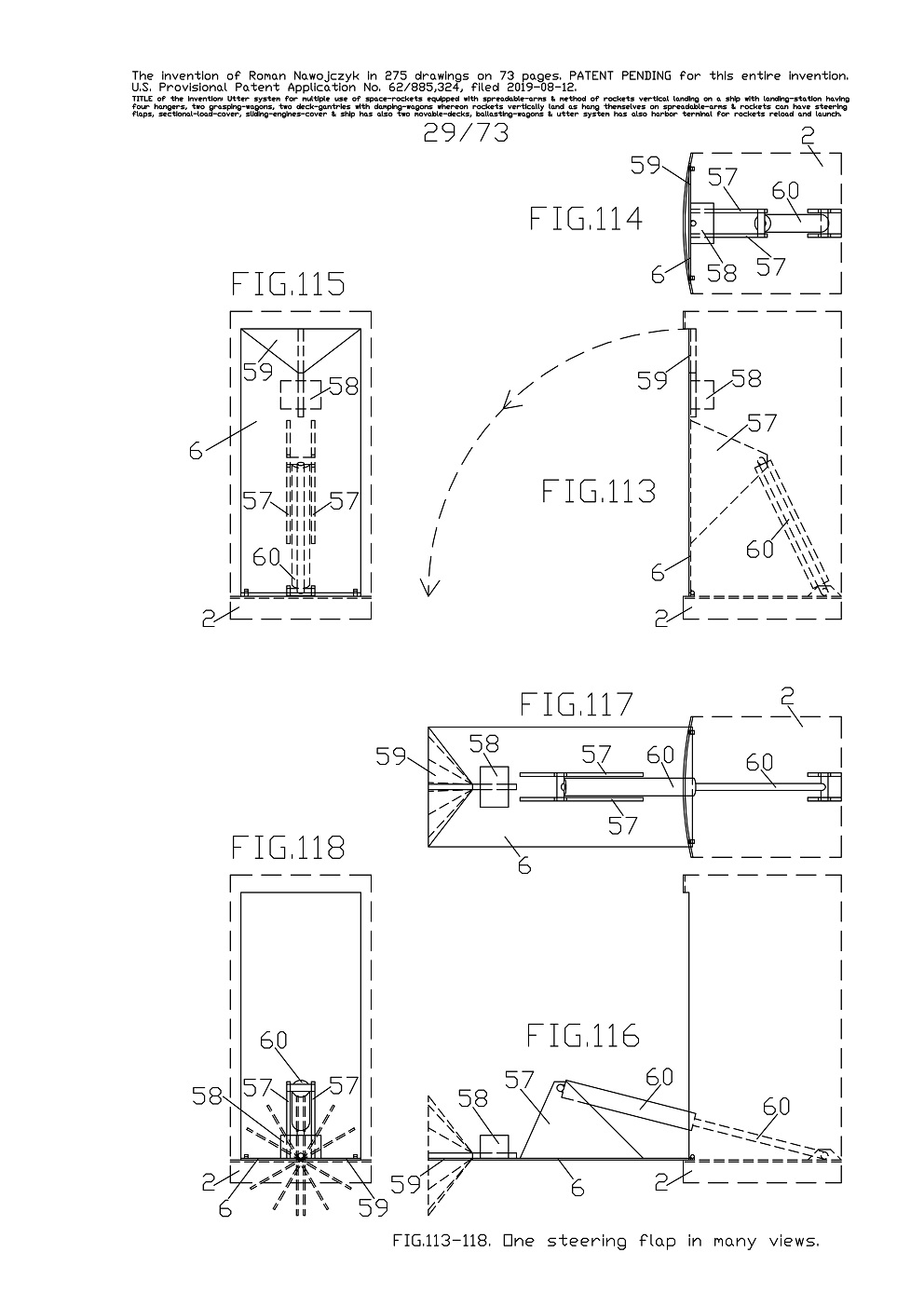
FIG.113, 114, 115, 116, 117, 118 show the enlarged views of one steering flap 6 together with the sketches of its deflection mechanism in the main-rocket 2 fragment.
And FIG.113, 114, 115 show three enlarged views of one steering flap 6 which is vertically set and entirely inside the rocket frame. Whereas FIG.113 is the side view, FIG.114 is the top view, FIG.115 is the front view. On FIG.113 the arrows show direction of deflection out of the flap 6.
And FIG.116, 117, 118 show three enlarged views of one flap 6 which is entirely deflected outside the rocket frame. Whereas FIG.116 is the side view, FIG.117 is the top view, FIG.118 is the front view. Furthermore here one torsional-triangle 59 is sketched in several variously twisted settings. Each deflection mechanism of the flap 6 consists of one linear-actuator 60 and of two ample-brackets 57.
Each flap 6 is cardinally installed by means of hinges to rocket frame.

Each flap 6 has permanently fastened two ample-brackets 57 whereto are rotatably installed the linear-actuator 60. The linear-actuator 60 second end is rotatably installed inside the rocket frame. The linear-actuators 60 steer deflections of the entire flaps 6. On upper parts of two opposite flaps 6 are installed rotary-actuators 58 which strongly grasp and steer axial torsion of the torsional-triangles 59. Therewith both torsional-triangles 59 serve for precise steering of entire rocket axial torsion, needed before landing on two movable ship-gantries 20.
The torsional-triangles 59 can be installed on all four flaps 6. The torsional-triangles 59 are triangular so that they could be used at all speeds and stages of the rocket descent in the Earth's atmosphere. During the first time period of the rocket descent in the Earth's atmosphere occur gigantic pushing forces on all flaps 6 and on both torsional-triangles 59 which are shown on further FIG.212-214.

.


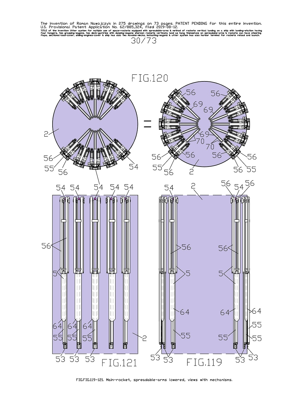
FIG.119, 120, 121 show three views of the fragment of one main-rocket 2 upper part which has entirely lowered all ten spreadable-arms 5 and consequently they are alongside the rocket frame. 
Whereas FIG.119 is the side view. And FIG.120 is the top view which is in two equal views which are rotated 90 degrees in relation to each other so that they cohere with the below views. And FIG.121 is the front view. 
Whereas FIG.119 shows only the sub-assemblies outside the rocket frame. Here is visible that all ten spreadable-arms 5 are suitably spaced out in the rocket frame so that they all could spread out on two sides. Furthermore it is visible that each spreadable-arm 5 consists of two lateral-beams 56 and one middle-beam 55 with permanently fastened a long-plate 64. The middle-beam 55 bottom is rotatably joined with a slider 53. Whereat the middle-beam 55 top is rotatably joined with the bottoms of both lateral-beams 56. While, both lateral-beams 56 tops are rotatably joined with the rocket frame. Furthermore, both lateral-beams 56 tops are bent and are inside the rocket frame. 

FIG.120 shows the moving mechanisms outside and inside rocket. These views show in this rocket interior, arrangement of ten moving mechanisms which spread out the spreadable-arms 5. 
Furthermore above each spreadable-arm 5 moving mechanism is installed a pushing mechanism having a blocking-bar 54 which serves for blocking the middle-beam 55 in spreadable-arm 5 while, it is entirely lifted. This pushing mechanism consists of the large-C-shaped beam 69, a linear-actuator 70 and of a vertical-low-bar 71. 
Here is shown in the rocket interior, the arrangement of ten large-C-shaped beams 69 which have inside the blocking-bars 54 moved slidingly and lineally by linear-actuators 70. 
And FIG.121 is the fragment front view of one main-rocket 2 upper part. This view shows only the sub-assemblies outside the rocket frame. Here outside the rocket frame is visible in what way are spaced out all ten spreadable-arms 5. 
On all views FIG.119-121, all blocking-bars 54 are entirely inside the rocket frame. Thus each blocking-bar 54 is situated in the large-C-shaped beam 69. 


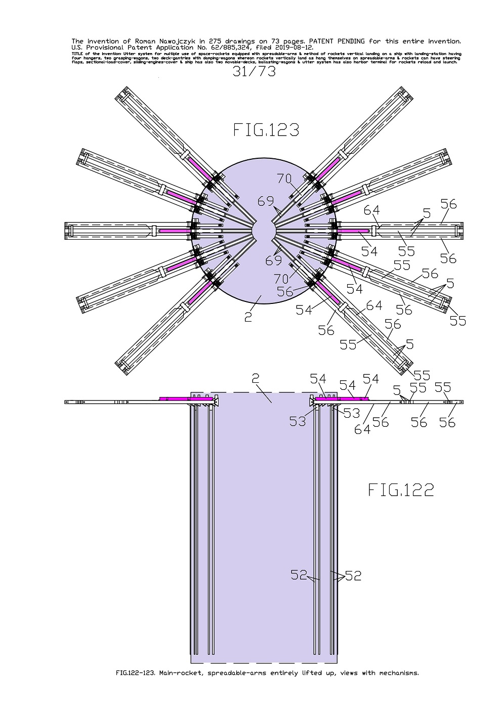
FIG.122, 123 show two views of the fragment of one main-rocket 2 upper part which has entirely lifted all ten spreadable-arms 5 and consequently they are completely spread out on two sides. And therefor these spreadable-arms 5 are transverse the rocket frame. Whereas FIG.122 is the side view. And FIG.123 is the top view. 
And FIG.122 shows only the sub-assemblies outside the rocket frame. Here outside the rocket frame is visible in what way are spaced out all ten spreadable-arms 5 after their lifting upward. Furthermore here are clearly visible the whole corner-beams 52 on the rocket frame because all spreadable-arms 5 are lifted. Two corner-beams 52 serve for leading one slider 53. 
And FIG.123 is the top view and shows the sub-assemblies outside and inside the rocket frame after lifting upward all ten spreadable-arms 5. Here is visible that all ten spreadable-arms 5 are suitably spaced out in the rocket frame so that they all could spread out on two sides. 

Furthermore is visible in the rocket interior, arrangement of ten moving mechanisms which spread out ten spreadable-arms 5. And is visible in the rocket interior, arrangement of ten large-C-shaped beams 69 wherein inside are the blocking-bars 54 which can be move slidingly and lineally by linear-actuators 70. 
Currently all blocking-bars 54 are entirely slid outside the rocket frame and it entirely blocked all middle-beams 55 in all spreadable-arms 5. While, the lateral-beams 56 upper bent parts are inside the rocket frame and currently are alongside the rocket frame. And consequently they are very near to moving mechanisms which spread out the entire spreadable-arms 5. 
On current FIG.123 it is visible that all lateral-beams 56 bent parts do not collide with themselves during moving. 
There are also visible some half empty interiors of all ten large-C-shaped beams 69 because all ten blocking-bars 54 half-lengths moved slidingly and lineally outside the rocket frame. Here are also marked the long-plate 64 and the sliders 53. Current FIG.122, 123 are similar to earlier FIG.102, 103. 


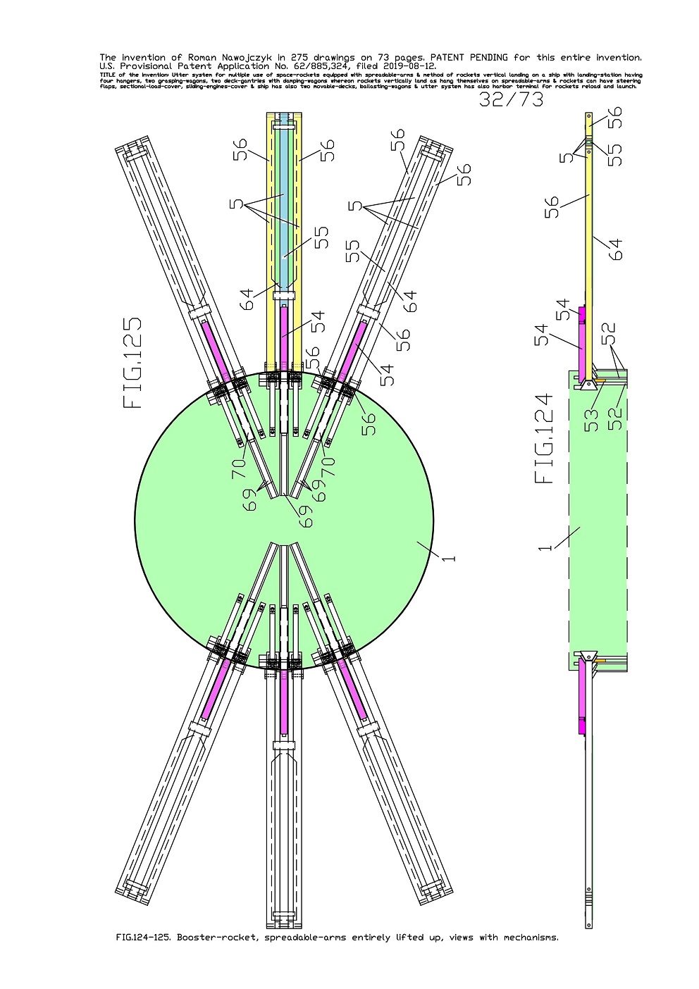
FIG.124, 125 show two enlarged views of the fragment of one booster-rocket 1 upper part which has entirely lifted all six spreadable-arms 5 and consequently they are completely spread out on two sides. And therefor these spreadable-arms 5 are transverse the rocket frame. 
Whereas FIG.124 is the side view, FIG.125 is the top view. And FIG.124 shows only the sub-assemblies outside the rocket frame. Here outside the rocket frame is visible in what way are spaced out all six spreadable-arms 5 after their lift upward. And FIG.125 shows the sub-assemblies outside and inside rocket after lifting upward all six spreadable-arms 5. Here is visible that all six spreadable-arms 5 are suitably spaced out in the rocket frame so that they all could spread out on two sides. 

Furthermore all views show in the rocket interior, arrangement of six moving mechanisms of six spreadable-arms 5. And show in the rocket interior, arrangement of six large-C-shaped beams 69 wherein inside are the blocking-bars 54 which can be move slidingly and lineally by linear-actuators 70. 
Currently all blocking-bars 54 are entirely slid outside the rocket frame and it entirely blocked all middle-beams 55 in all spreadable-arms 5. There are visible the half empty interiors of all six large-C-shaped beams 69 because all six blocking-bars 54 half-lengths moved slidingly and lineally outside the rocket frame. Here are marked also the long-plates 64, the sliders 53 and the corner-beams 52 on the rocket frame. 
Current FIG.124, 125 are similar to previous FIG.122, 123 and FIG.100, 101. 


FIG.126, 127, 128 show three views of one entire spreadable-arm 5 together with its moving mechanism and with one blocking-bar 54 and its pushing mechanism. These views are in the rocket frame fragments with the sub-assemblies outside and inside. This spreadable-arm 5 is entirely lowered to P1 first setting and consequently it is alongside the rocket frame. While, the blocking-bar 54 is inside the rocket frame. 
Whereas FIG.126 is the side view with the partial vertical sectional view. And FIG.127 is the top view in two equal views which are rotated 90 degrees in relation to each other so that they cohere with the below views. FIG.127 is the view only of the components situated upwards of the common-long-axle 65. And FIG.128 is the front view but only of the sub-assemblies outside the rocket. 
Furthermore here are auxiliary one sectional view and the bottom projection both without some drawing numbers. 
On FIG.126 the arrows show the moving directions of the spreadable-arm 5 components. And the arrows show a moving direction of the blocking-bar 54. Here is also visible the fragment of a pressure-tank 61 inside the rocket frame. It shows and explains that all mechanisms are designed in such way that they fit into vacant space above this pressure-tank 61. 
Each spreadable-arm 5 mainly consists of two lateral-beams 56 and one middle-beam 55 which are joined in suitable way with themselves and with the additional components. 

Both lateral-beams 56 bottoms are rotatably joined with the middle-beam 55 top by means of the common-long-axle 65. Between the middle-beam 55 and both lateral-beams 56 on the common-long-axle 65 are inserted two distance-blocks 81. The middle-beam 55 bottom is rotatably joined with the slider 53 by means of the holding-axle 66. The slider 53 can move slidingly between two corner-beams 52 on the rocket frame. To middle-beam 55 is permanently fastened a T-bar 67 and the long-plate 64 for aerodynamic purposes. Inside the middle-beam 55 bottom is installed a frictional-brake 68. 
Whereat, both lateral-beams 56 tops are rotatably joined with the rocket frame by means of two bearing-axles 63 which are situated in four bearing-brackets 80. Both lateral-beams 56 have upper bent parts and which are situated inside the rocket frame. To each upper bent part are permanently fastened two flat-bars 72 which have some oval-openings. 
In current setting, both lateral-beams 56 upper bent parts with all flat-bars 72 are transverse the rocket frame. These lateral-beams 56 bent parts are very near the moving mechanism which spreads out the entire spreadable-arm 5. 
Here is also shown that above each spreadable-arm 5 moving mechanism is installed the pushing mechanism of the blocking-bar 54. This pushing mechanism consists of the large-C-shaped beam 69, a linear-actuator 70 and of a vertical-low-bar 71. 
Currently the entire blocking-bar 54 is inside the large-C-shaped beam 69 and consequently it is inside the rocket frame. 


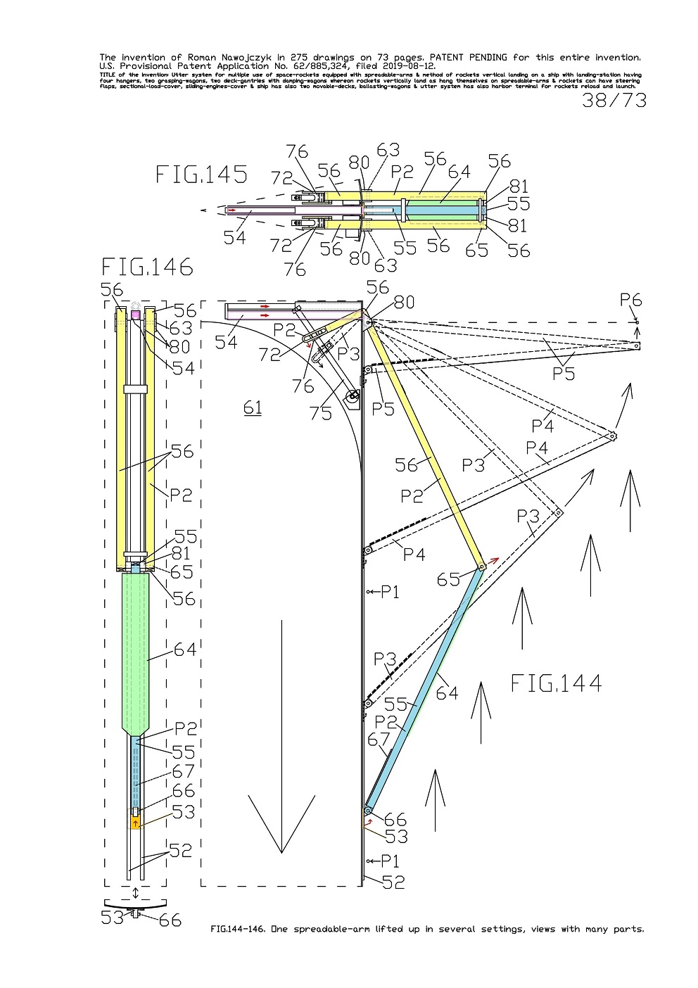
FIG.144, 145, 146 show outside and partly inside the rocket fragment, the three views of one entire spreadable-arm 5 in P2 setting which is in one-quarter lifted and consequently protrudes outside the rocket frame. Whereas FIG.144 is the side view and the partial vertical sectional view of the rocket frame. 
And FIG.145 is the top view. And FIG.146 is the front view but only outside the rocket frame. This FIG.146 has also an auxiliary bottom projection without some drawing number. 
On FIG.144 are also sketched intermediate settings of the spreadable-arm 5, it means in P3, P4 and P5 settings. There is also marked P6 final setting thus while, the spreadable-arm 5 is entirely lifted. Here the arrows show a spreading direction of this spreadable-arm 5 from its P1 first setting up to its last P6 setting. 

Inside the rocket fragment FIG.144 shows all components and moving mechanism of the spreadable-arm 5. 
The lateral-beams 56 upper bent parts with the flat-bars 72 are in P2 setting and are also sketched in P3 setting. There is also the pressure-tank 61 fragment in the rocket interior and it shows and explain that the flat-bars 72 during their moving do not hook with this pressure-tank 61. On the rocket frame one large arrow shows the rocket descent direction in the Earth's atmosphere while, the external arrows show from what direction comes flying atmospheric air and consequently in what way this air strongly crowds into spreadable-arm 5 in P2, P3, P4 and P5 settings. 
Currently the entire blocking-bar 54 is inside the rocket frame. Here are visible a lot the components mentioned in FIG.126, 127, 128. Here and on several next FIGs. the lateral-beams 56 ends and the middle-beams 55 ends are marked with crossed lines as an X letter so that those ends would be better visible. 


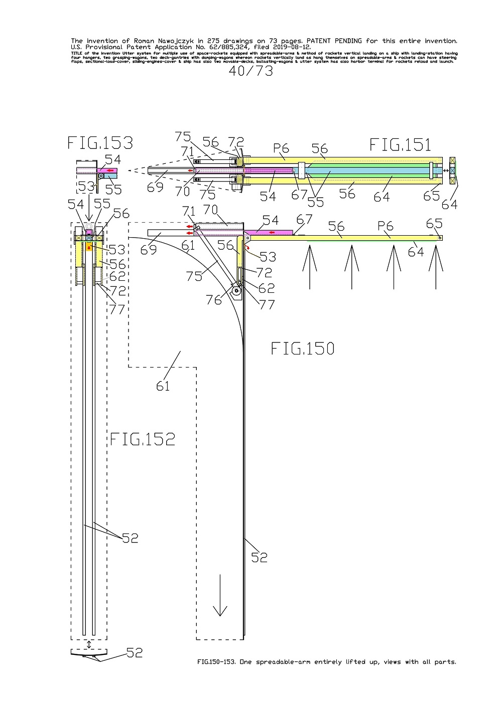
FIG.150, 151, 152, 153 show outside and inside the rocket fragment the views of one entire spreadable-arm 5 in the P6 setting which is entirely lifted and consequently it is transverse the rocket frame. Whereat the blocking-bar 54 is slid maximally outside the rocket frame and it entirely blocked the middle-beam 55 in the spreadable-arm 5. Whereas FIG.150 is the side view with the partial vertical sectional view of the rocket frame. And FIG.151 is the top view and with all components and mechanisms and this view has one auxiliary right-side-view without some drawing number. And FIG.152 is the front view outside the rocket frame.This view in the rocket interior has the sketches of the flat-bars 72 together with both lateral-beams 56 upper bent parts. On the rocket frame are visible two whole corner-beams 52 which lead the slider 53 of the spreadable-arm 5. This view has also the auxiliary bottom projection without some drawing number. On FIG.150 on the rocket frame one large arrow shows the rocket descent direction in the Earth's atmosphere. Whereas the external arrows show from what direction comes flying atmospheric air and consequently in what way this air strongly crowds into the spreadable-arm 5 entirely lifted.

FIG.153 is auxiliary and is the side view and the partial vertical sectional view which shows FIG.152 only in the middle. Namely FIG.153 shows the fragments of the middle-beam 55 and of the slider 53 and furthermore of the blocking-bar 54 fragment.
All views show that the flat-bars 72 together with the lateral-beams 56 upper bent parts are directed down inside the rocket frame and consequently are alongside of the rocket frame. On FIG.150 is well visible that all flat-bars 72 are leaned against on limiters 62 in the rocket frame. The blocking-bar 54 is slid maximally outside the rocket frame and it entirely blocked the middle-beam 55 in the spreadable-arm 5. There is visible an empty part of the large-C-shaped beam 69 because the blocking-bar 54 moved slidingly and lineally outside. Whereas the linear-actuator 70 folded entirely up. The middle-beam 55 after its blocking gains possibility of carrying burdens in all directions. Possibility of carrying burdens by this middle-beam 55 is very favorable for the entire spreadable-arm 5. During aerodynamic braking and during hanging of the rocket on two damping-wagons 30 or 31, all spreadable-arms 5 will be maximally burden. Recommended is therefor so that all middle-beams 55 would carry also burdens together with all lateral-beams 56. Current views descriptions are tied with descriptions of the pushing mechanism of the blocking-bar 54 in earlier FIG.129-131.


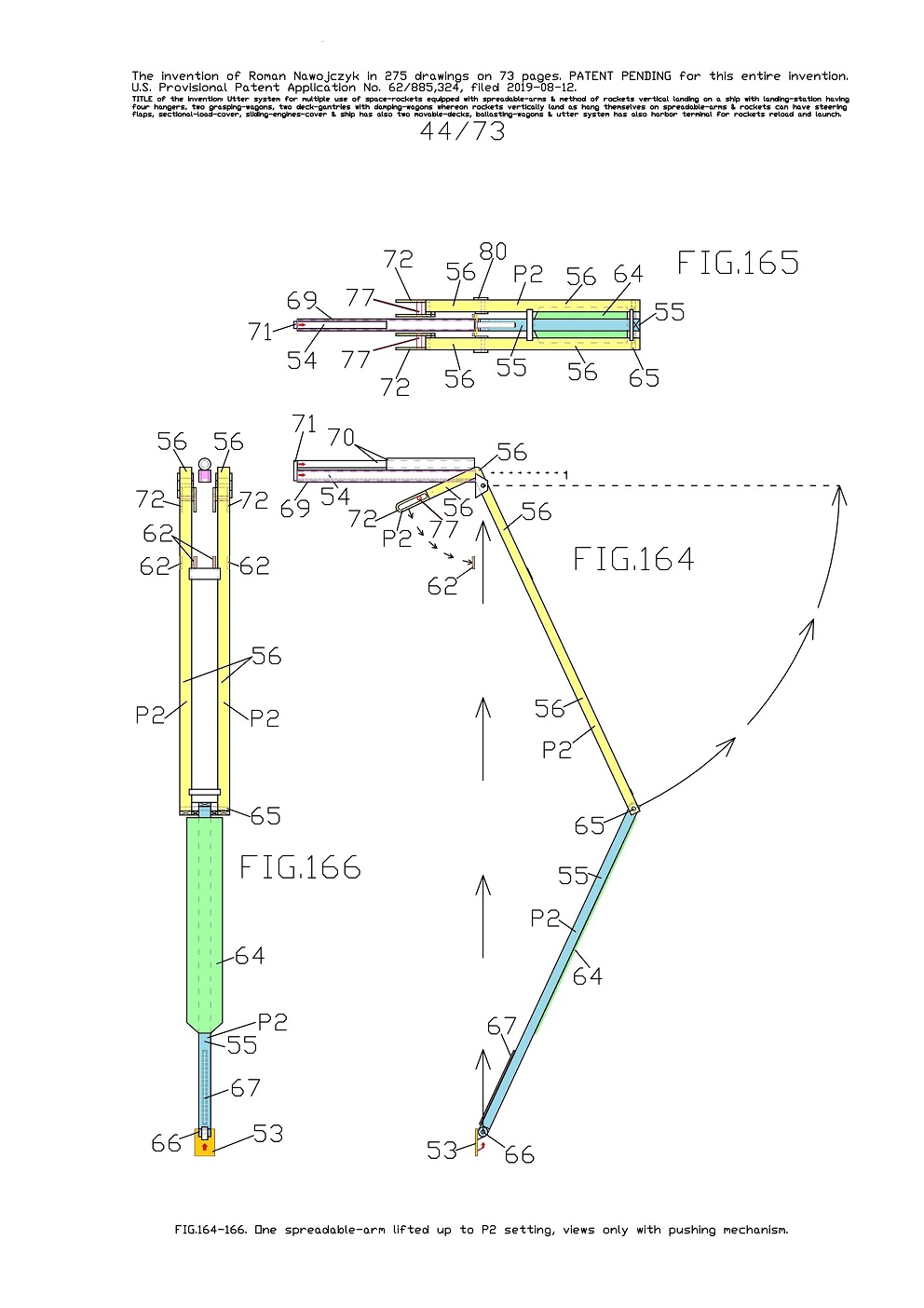
FIG.164, 165, 166 show three views of the alone spreadable-arm 5 which is in one-quarter lifted to P2 setting. These views are similar to FIG.144, 145, 146 however do not contain the moving mechanism of this spreadable-arm 5 except of the cylindrical-pegs 77. There are also not the rocket fragments except of four bearing-brackets 80 and four limiters 62. 

While, here is also the entire pushing mechanism of the blocking-bar 54 that is not slid outside. 
And FIG.164 is the side view and here is visible in what way stoop down the lateral-beams 56 upper bent parts and together with them stoop down the flat-bars 72 which have the oval-openings. Here the arrows show the directions of further moving of the spreadable-arm 5 components and of the blocking-bar 54. And FIG.165 is the top view, FIG.166 is the front view.


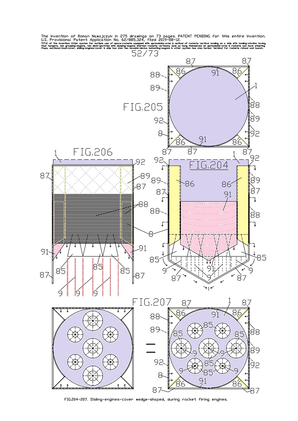
FIG.204, 205, 206, 207 show the views of one sliding-engines-cover 8 which can be lowered and here is in version wedge-shaped underneath after its lowering. This sliding-engines-cover 8 is installed to rocket frame bottom because there are its main engines. All current views show only the booster-rocket 1 bottom. Currently the sliding-engines-cover 8 is entirely lifted and it causes that all main-engines nozzles 85 are entirely uncovered. 
Whereas FIG.204 is the side view. And FIG.205 is the top view only of the current rocket fragment. And FIG.206 is the front view. And FIG.207 is the bottom projection of the current rocket bottom in two equal views which are rotated 90 degrees in relation to each other so that they cohere with the above views. This version of the sliding-engines-cover 8 is very similar in construction to version flat underneath. 

Current version, the sliding-engines-cover 8 creates a wedge underneath the rocket after coming to each other and touching on themselves of both jalousies 88. This wedge underneath the rocket entirely cover underneath the rocket main engines. Furthermore both sliding rounded-plates 91 are pointed in some bottom edges so that they adjoin to both jalousies 88. 
Here in the rocket frame are applied two kinds of the main engines nozzles 85 so that the exhaust-fumes 9 completely pass by U-form-rails 87. On all views, the arrows show the sliding directions of both jalousies 88 and both rounded-plates 91. 
Here is visible that the exhaust-fumes 9 gush down but beside both U-form-rails 87 and consequently they cannot melt them. 
Furthermore the U-form-rails 87 do not brake gushing down of the exhaust-fumes 9 of all nozzles 85. 


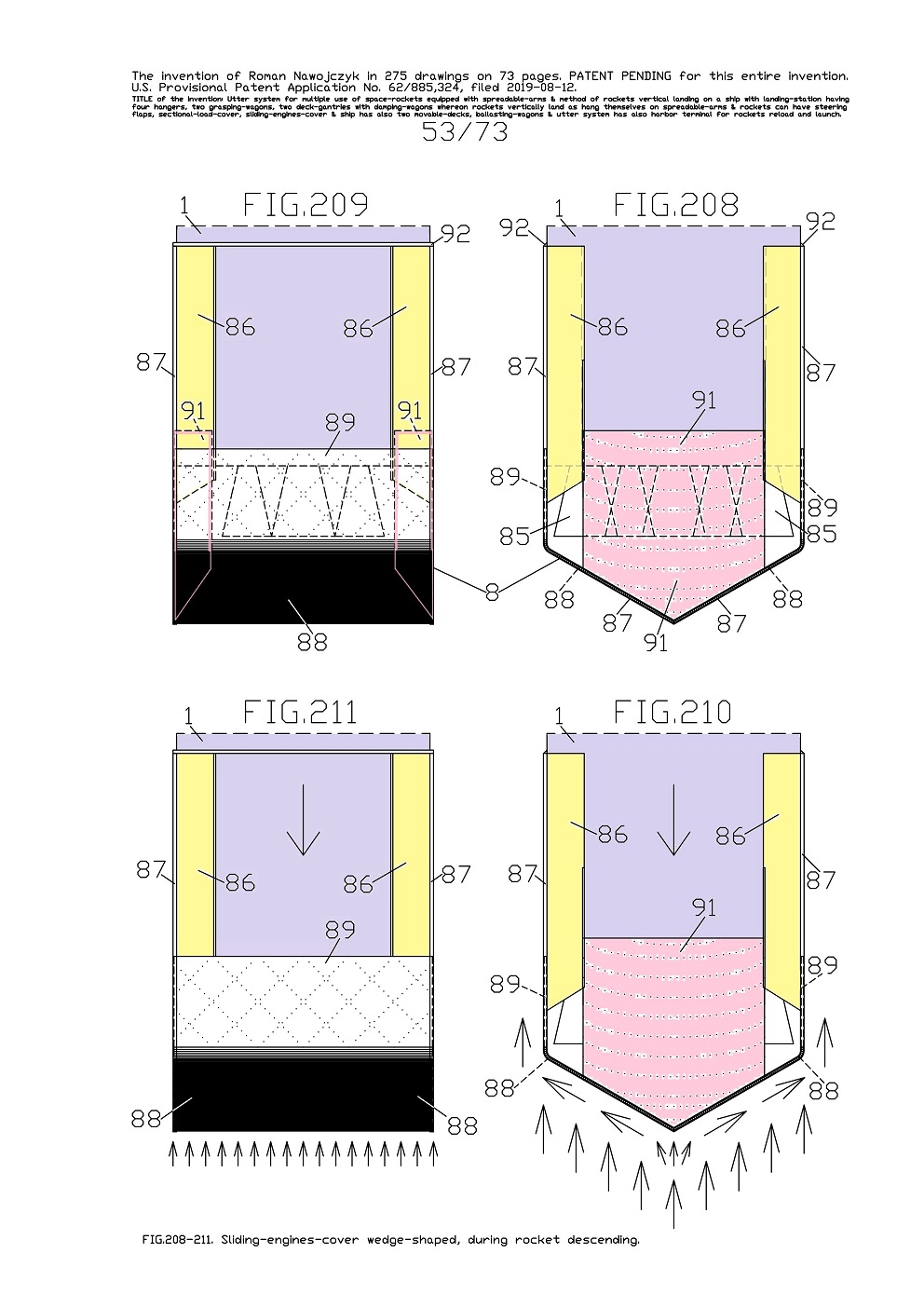
FIG.208, 209, 210, 211 show the views of the sliding-engines-cover 8 which can be lowered and here is in version wedge-shaped underneath after its lowering. This sliding-engines-cover 8 is installed to rocket frame bottom because there are its main engines. Current views show only the booster-rocket 1 bottom. 
On all views the sliding-engines-cover 8 is entirely lowered and it causes that the rocket bottom is entirely covered. 
The views on FIG.208, 209 show some main components emplacement of the sliding-engines-cover 8 in relation to themselves and with the components sketches which are veiled by some other members. 
And FIG.208 is the side view, FIG.209 is the front view. 
Whereat the views on FIG.210, 211 do not have the components sketches which are veiled by some other members. And FIG.210 is the side view, FIG.211 is the front view. 
These views show in what way this sliding-engines-cover 8 expands and divides in two sides some atmospheric air during the rocket descent in the Earth's atmosphere. Underneath the rocket arises a large wedge-shape after coming to each other and touching on themselves of both jalousies 88. 
This large wedge-shape covers the main engines underneath. Furthermore this large wedge-shape will divide and bent air stream in two directions outside the rocket frame. 

The large wedge-shape is the main-cover with jalousies 88 of the rocket main engines whereas this rocket will enter into the Earth's atmosphere. 
Here on the rocket frame, the large arrows show this rocket descent direction in the Earth's atmosphere. 
Whereat the external arrows show from what direction comes flying atmospheric air and consequently in what way this air strongly crowds into both jalousies 88 which came to each other inside the U-form-rails 87. 
While, both rounded-plates 91 shield almost entirely the rocket bottom sides which are not covered entirely by main-cover with jalousies 88. Such rocket status will occur during the rocket entering in the Earth's atmosphere and its further descent until the moment while there will be necessary the main engines firing blast for braking action at landing. 
Lift upward of the sliding-engines-cover 8 can occur rapidly quickly. 


The information that was not included in the patent application. 
For both sliding-engines-covers 7 and 8, I have two further possible improvements and strengthening, The first one is rather advance. The second one is very easy and cheap to build. It will strengthen the jalousies just in the middle of them. These improvements and strengthening do not rely on using some thicker part walls. 
Current solutions of the sliding-engines-covers 7 and 8 do not determine what kind of the construction materials should be used for building them, or how thick some part walls should be in order to withstand atmospheric reentry. 


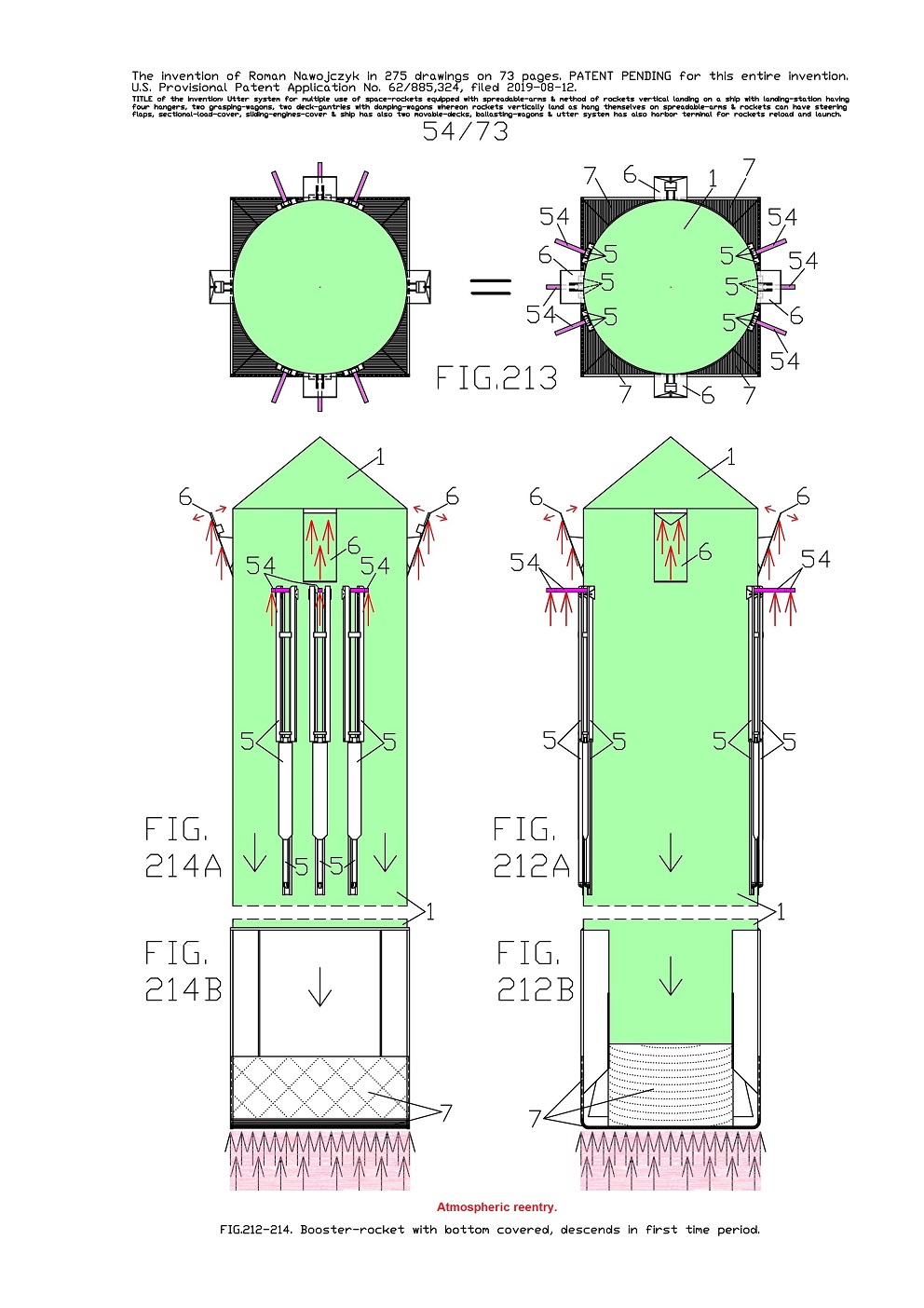
FIG.212A, B, 213, 214A, B show the views of the upper and bottom parts of one booster-rocket 1 which descends in the first time period at giant speed in the Earth's atmosphere. 
Whereas FIG.212A is the side view of the upper part, and FIG.212B is the side view of the bottom part. And FIG.214A is the front view of the upper part, and FIG.214B is the side view of the bottom part. And FIG.213 is the top view in two equal views which are rotated 90 degrees in relation to each other so that they cohere with the below views. 
This booster-rocket 1 has six spreadable-arms 5, four steering flaps 6, six blocking-bars 54 and the sliding-engines-cover 7 flat underneath. Currently all six spreadable-arms 5 are entirely lowered and consequently are alongside the rocket frame; four flaps 6 are a little deflected out from the rocket frame for steering this rocket descent direction; all six blocking-bars 54 are entirely slid outside so that causing small aerodynamic braking which will stabilize this rocket descent; the sliding-engines-cover 7 is entirely lowered and it causes that the rocket bottom is entirely covered. 

Such arrangement of all components and sub-assemblies of this entire booster-rocket 1 will occur during its descent in the first time period at giant speed in the Earth's atmosphere. 
On FIG.212A, B and FIG.214A, B, on the rocket frame large arrows show the rocket descent direction in the Earth's atmosphere. 
Whereat remaining arrows show in several places what happens with the rocket and its sub-assemblies in such situation. 
These arrows show from what direction comes flying atmospheric air and consequently in what way this air strongly crowds into sliding-engines-cover 7, into six blocking-bars 54 and into four flaps 6. 

Simultaneously the arrows also show the deflection directions of the flaps 6 for steering the rocket descent direction. 


Next arrangement status of all components and sub-assemblies of this entire booster-rocket 1 will occur during its descent in the second time period at average speed in atmosphere and which is shown on next FIGs. 


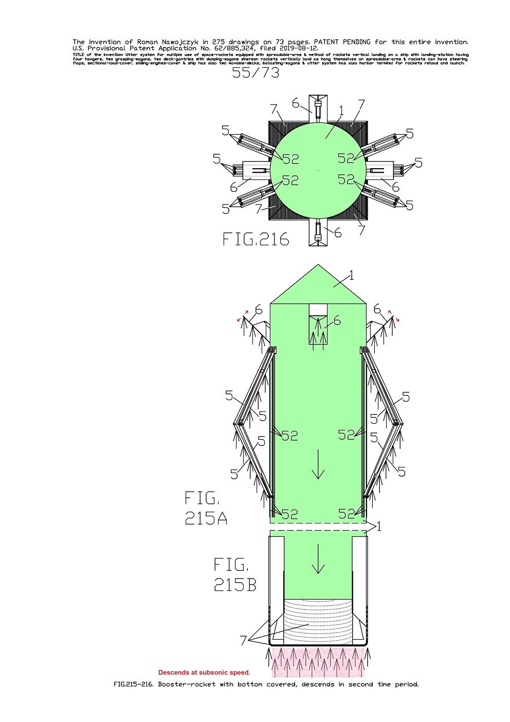
FIG.215A, B and 216 show the views of the upper and bottom parts of one booster-rocket 1 which descends at average speed in the Earth's atmosphere. 
Whereas FIG.215A is the side view of the upper part, and FIG.215B is the side view of the bottom part. And FIG.216 is the top view. This booster-rocket 1 has six spreadable-arms 5, four steering flaps 6 and the sliding-engines-cover 7 flat underneath. 
Currently all six spreadable-arms 5 are lifted somewhat upward and consequently protrude outside the rocket frame; four flaps 6 are a lot deflected out the rocket frame; the sliding-engines-cover 7 is entirely lowered and it causes that the rocket bottom is entirely covered. Whereas all six blocking-bars 54 are entirely in the rocket interior because now they would not cause any aerodynamic braking. 
Moreover here are well visible the corner-beams 52 on the rocket frame because all spreadable-arms 5 are lifted somewhat upward.
Such arrangement of all components and sub-assemblies of this entire booster-rocket 1 will occur during its descent in the second time period at average speed in the Earth's atmosphere. This average speed of the rocket descent enables lift somewhat upward of all spreadable-arms 5 as on the current views. 

On FIG.215A, B on the rocket frame, the large arrows show the rocket descent direction in the Earth's atmosphere. 
Whereat remaining arrows show in several places what happens with the rocket and its sub-assemblies in such situation. These arrows show from what direction comes flying atmospheric air and consequently in what way this air strongly crowds into sliding-engines-cover 7, into six spreadable-arms 5 which are lifted somewhat upward, into four flaps 6 which are a lot deflected out the rocket frame. Simultaneously the arrows also show the deflection directions of the flaps 6 for steering the descent direction. 
During the rocket descent and at the same time lifting upward of each spreadable-arm 5, airflow exerts very large pressure on two lateral-beams 56 and the middle-beam 55 with the long-plate 64. The long-plate 64 permanently fastened on the middle-beam 55 causes that pressure exerted on them even out with pressure exerted on two lateral-beams 56. Without the long-plate 64 pressure exerted on two lateral-beams 56 would be probably twice greater than on one middle-beam 55 and it might too strongly push the entire spreadable-arm 5 upward. 
A final arrangement status of all components and sub-assemblies of this entire space-rocket will occur during its descent in the third time period at slow speed in the Earth's atmosphere and which is shown on further FIG.262-267. Then slow speed of the rocket descent in the Earth's atmosphere will enable total lift upward of all spreadable-arms 5. 


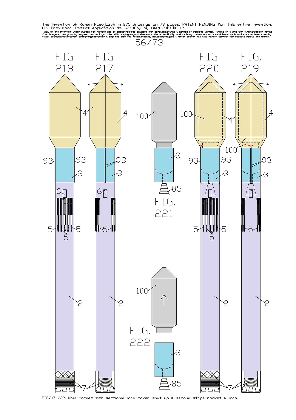
FIG.217, 218, 219, 220 show the views of one entire main-rocket 2 which has installed a sectional-load-cover 4 which is dividable into two sections and spreadable out on two opposite sides. The sectional-load-cover 4 serves for covering inside some load 100 and this way creates its thermal protection during the rocket ascent and descent in the Earth's atmosphere. Thus inside the sectional-load-cover 4 can be fastened some payload that will be carried out on the Earth's orbit and later can be fastened some return-load that will be carried down on Earth. The sectional-load-cover 4 is installed on main-rocket 2 upper part and can be situated above the second-stage-rocket 3. 
The sectional-load-cover 4 can be completely lowered to main-rocket 2 upper part as well. This sectional-load-cover 4 is attached to main-rocket 2 by means of four long cog-beams 93. 
Currently to main-rocket 2 is also directly attached the second-stage-rocket 3. Here the sectional-load-cover 4 is shut up and all cog-beams 93 are outside and on both sides of the second-stage-rocket 3. 

While, inside the sectional-load-cover 4 is placed a payload 100 which will be carried out on the Earth's orbit. This payload 100 is attached to second-stage-rocket 3. 
Whereas FIG.217 shows the side view of one entire main-rocket 2 which is ready for launch. And FIG.218 shows the front view of the same main-rocket 2. 
Whereat FIG.219 is the same as FIG.217 albeit contains the
payload 100 sketches inside the shut up sectional-load-cover 4 and the second-stage-rocket 3 sub-assemblies sketches which are veiled by some other modules. 
Whereat FIG.220 is the same as FIG.218 albeit contains the same sketches as FIG.220. Moreover on FIG.217, 219 the external arrows show the spreading directions of the sectional-load-cover 4 into two sections on two sides. 
FIG.221 is the side view of the second-stage-rocket 3 whereon is attached the
payload 100 which will be carried out on the Earth's orbit. Here is visible that the second-stage-rocket 3 has one nozzle 85 which is foldable. 
FIG.222 is the side view of the second-stage-rocket 3 where-from ascends the
payload 100. 


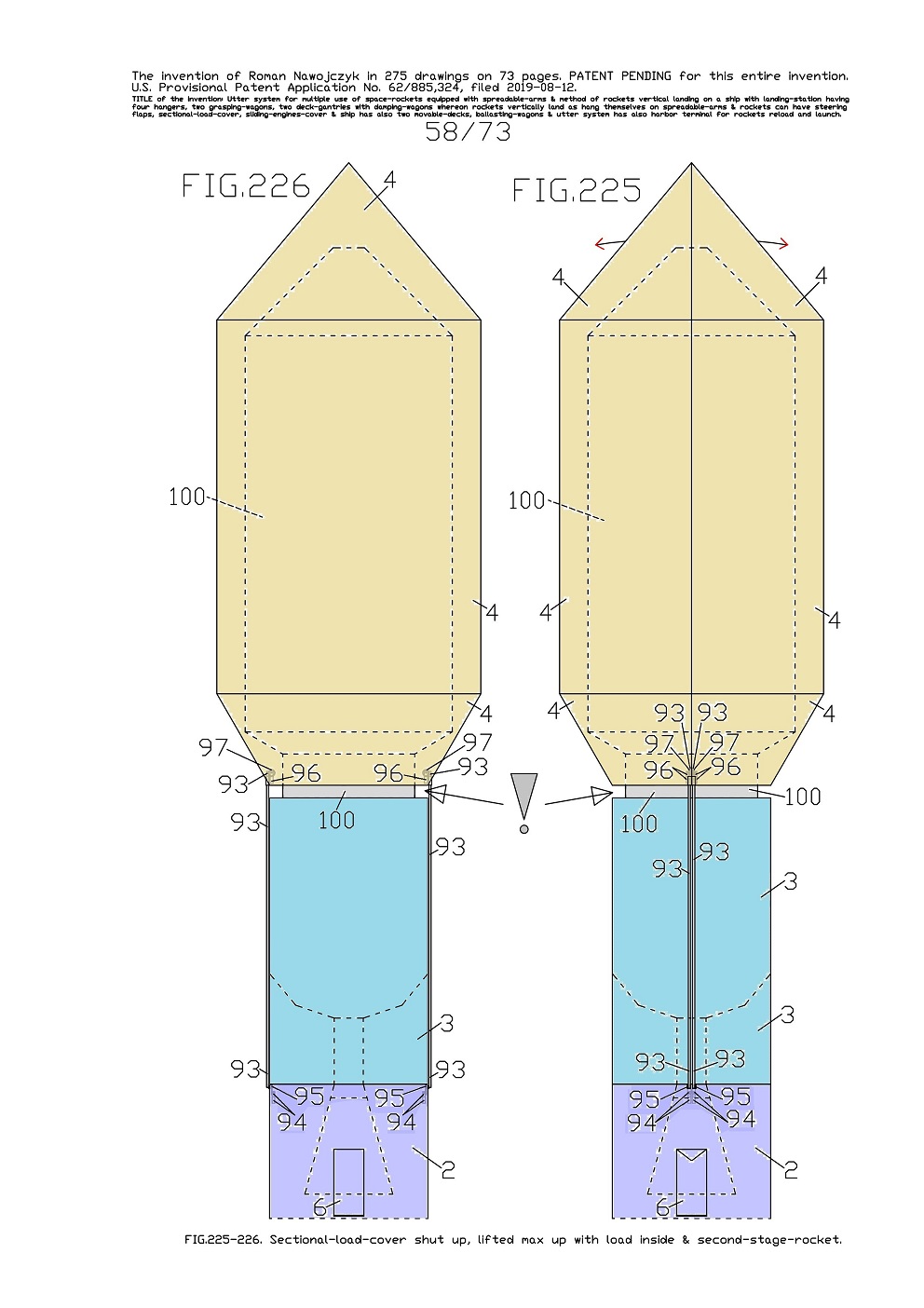
FIG.225, 226 show the enlarged views of the main-rocket 2 upper part shown also earlier on similar FIG.223-224. Currently the sectional-load-cover 4 is lifted maximally upward on four long cog-beams 93. This enables spreading it out on two sides. 
On current FIG.225, the external arrows show spreading directions of the sectional-load-cover 4 into two sections on two sides. 
Whereas FIG.225 is the side view, FIG.226 is the front view. 

Here is visible vacant space between the sectional-load-cover 4 bottom edge and the second-stage-rocket 3 upper edge. 

This vacant space is visible on the current views and is indicated with the large exclamatory sign. In this vacant space is already directly visible the fragment of the payload 100 that will be carried out on the Earth's orbit. 
The sectional-load-cover 4 became lifted maximally upward on four cog-beams 93 because rotating four cog-wheel 97 climbed up on four cog-beams 93. The four cog-wheel 97 are driven by four hoisting-gears 96.

The information that was not included in the patent application. 
For this sectional-load-cover 4, I have a possible improvement which is a new method of its strengthening after spreading it out. This improvement and strengthening do not rely on using some thicker part walls. 


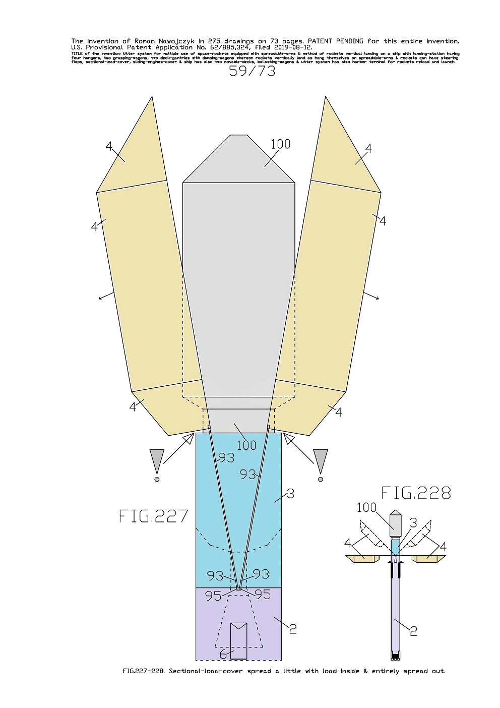
FIG.227 shows enlarged side view of the main-rocket 2 upper part shown earlier on similar FIG.223, 225. Here the sectional-load-cover 4 is already spread a little out on two sides. It is possible because there is vacant space between the sectional-load-cover 4 bottom edge and the second-stage-rocket 3 upper edge. This vacant space is visible on the current view and is indicated with two large exclamation marks. 
This view well shows, in what way the sectional-load-cover 4 can be spread out on two sides because it is two-sectional and is installed to main-rocket 2 by means of four cog-beams 93. Simultaneously it is visible that the cog-beams 93 are rotatably installed to main-rocket 2 frame. These cog-beams 93 are permanently fastened to rotating-axles 95 which are rotated by rotating-heads 94. 

All rotating-axles 95 became rotated tiny angle and it rotated the same tiny angle all entire cog-beams 93 and with them also both sections of the sectional-load-cover 4. 
Here the entire cog-beams 93 are continuously outside and on both sides of the second-stage-rocket 3. 
Currently is already a lot uncovered the
payload 100 which will be carried out on the Earth's orbit. 
FIG.228 shows very diminished the side view of one entire main-rocket 2 that has entirely spread out on two sides the sectional-load-cover 4 and shows the sketch its intermediate spreading out. Because of total spreading out on two sides the sectional-load-cover 4 there is entirely uncovered the
payload 100 which is attached to second-stage-rocket 3. 


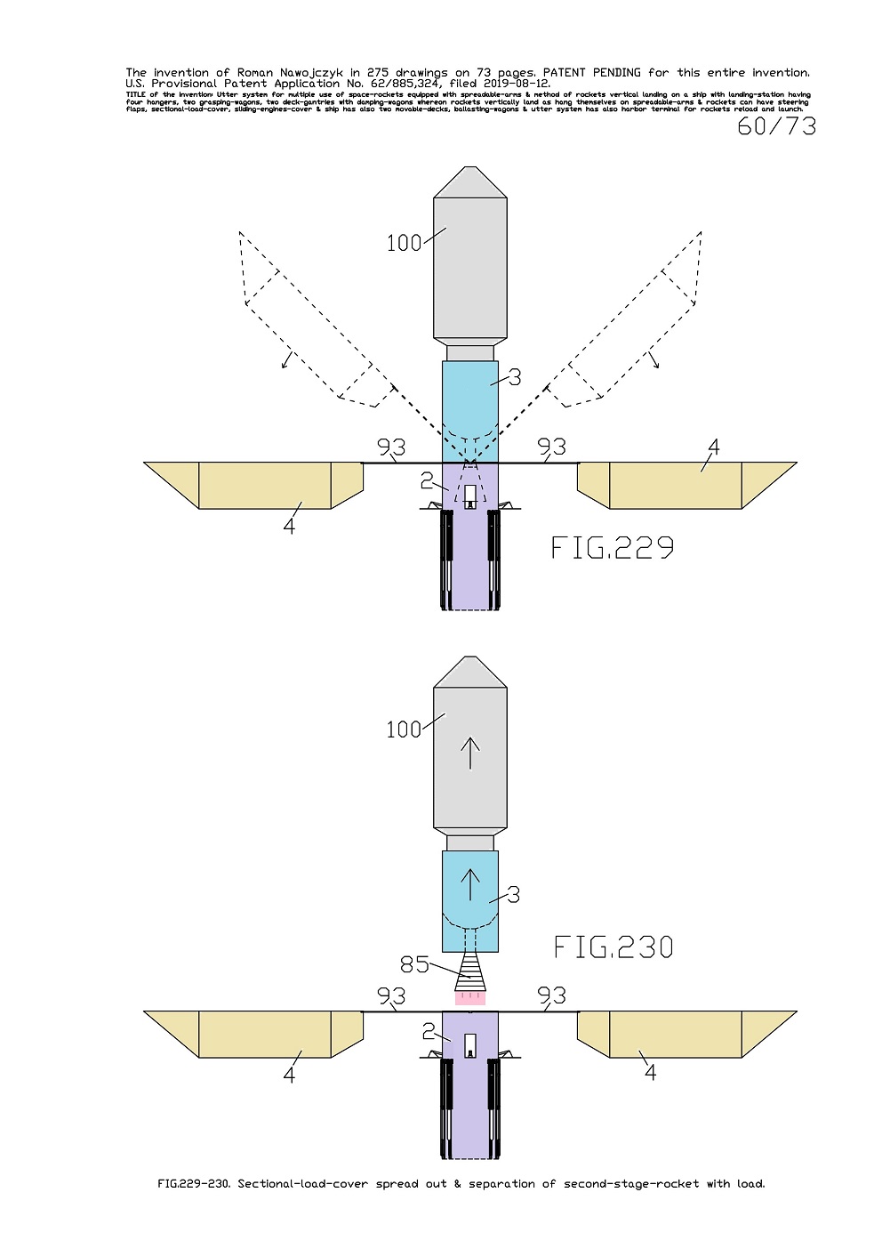
FIG.229 shows the side view of the main-rocket 2 upper part which has entirely spread out on two sides the sectional-load-cover 4 and the sketch its intermediate spreading out. Because of total spreading out on two sides the sectional-load-cover 4, there is entirely uncovered the payload 100 which is attached to second-stage-rocket 3. 
While, this second-stage-rocket 3 is still attached to main-rocket 2. 

FIG.230 shows the side view of the main-rocket 2 upper part which has also entirely spread out the sectional-load-cover 4. And here the second-stage-rocket 3 with attached payload 100 ascend together upward because they already separated from the main-rocket 2. 
All earlier views well show in what way the sectional-load-cover 4 can be spread out on two sides because it is two-sectional and is installed to main-rocket 2 by means of four cog-beams 93. Simultaneously it is visible that the cog-beams 93 are rotatably installed to main-rocket 2 frame.


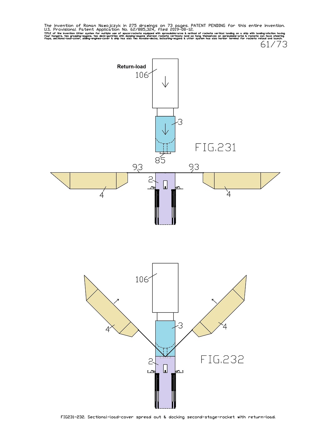
FIG.231 shows the side view of the main-rocket 2 upper part which has entirely spread out on two sides the sectional-load-cover 4. Here the second-stage-rocket 3 with attached a return-load 106 approach together to main-rocket 2 in order to dock with it. The second-stage-rocket 3 has the nozzle 85 which is folded for more safely docking. 

FIG.232 shows the side view of the main-rocket 2 upper part whereto is already docked the second-stage-rocket 3 with attached the return-load 106. Here the sectional-load-cover 4 is already a little shut up. 
Sequentially the sectional-load-cover 4 will be shut totally up and consequently will hide inside the entire return-load 106 from the Earth's orbit. 


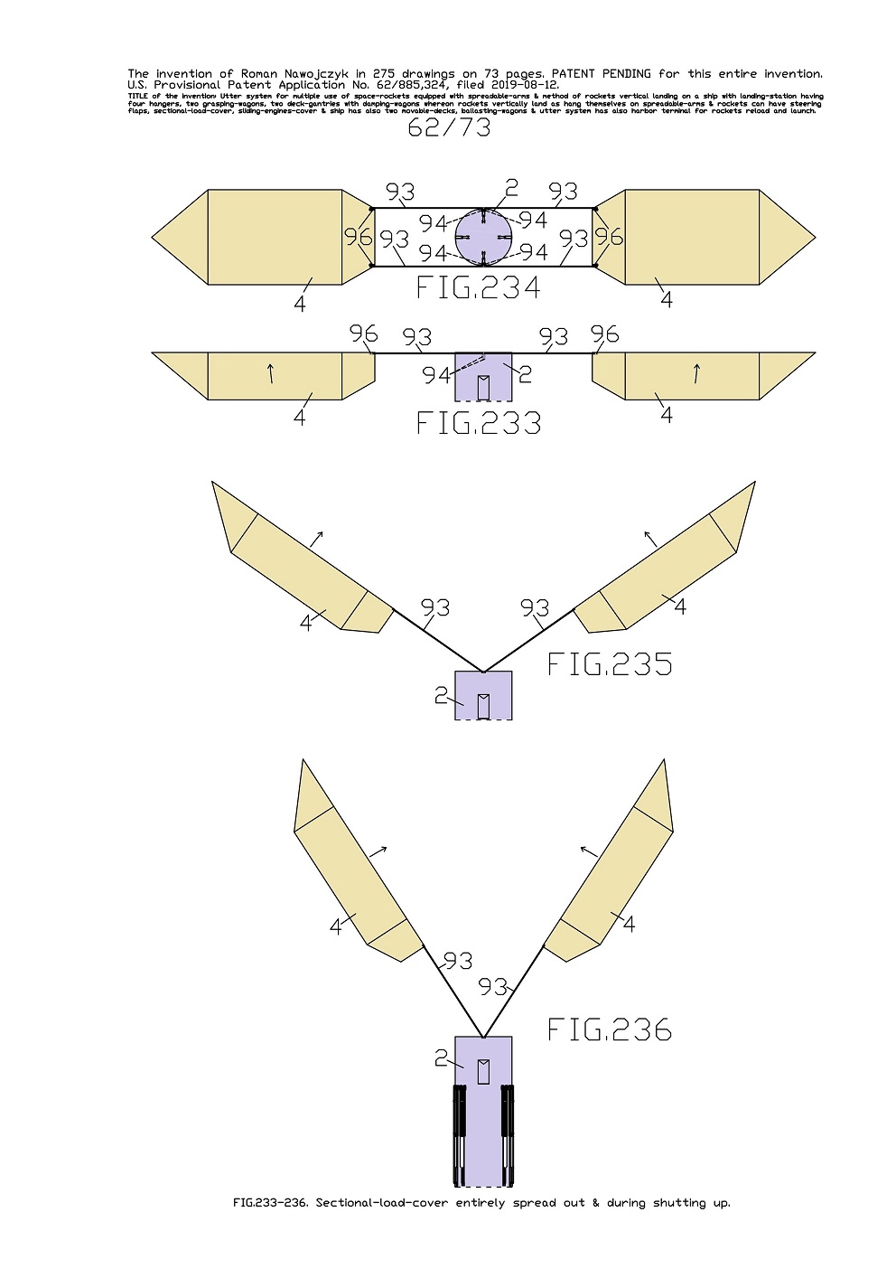
FIG.233, 234, 235, 236 show the views of the alone main-rocket 2 upper part ergo without docked the second-stage-rocket 3. 
Whereas FIG.233 shows the side view of the alone main-rocket 2 upper part which has entirely spread out on two sides the sectional-load-cover 4. 
And FIG.234 shows the top view of the alone main-rocket 2 upper part which has entirely spread out on two sides the sectional-load-cover 4. 
And FIG.233, 234 well show in what way the sectional-load-cover 4 can be spread out on two sides because it is two-sectional and is installed to main-rocket 2 by means of four cog-beams 93. 

Simultaneously it is visible that the cog-beams 93 are rotatably installed to main-rocket 2 frame. And here is clearly visible emplacement of four uncovered hoisting-gears 96 of the sectional-load-cover 4 both sections. 
Furthermore it is clearly visible emplacement of four uncovered rotating-heads 94 of the cog-beams 93. 
And FIG.235 shows the side view of the main-rocket 2 upper part which has a little shut up the sectional-load-cover 4. 
And FIG.236 shows the side view of the main-rocket 2 upper part which has even more shut up the sectional-load-cover 4.

.


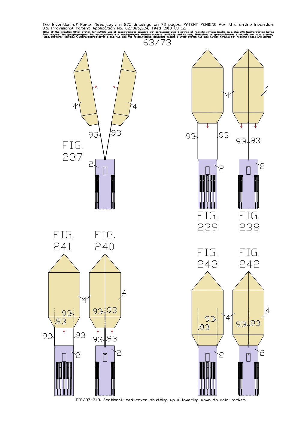
FIG.237-243 show the views of the alone main-rocket 2 upper part ergo without docked the second-stage-rocket 3. 
Whereas FIG.237 shows the side view of the main-rocket 2 upper part which is very near to shutting up the sectional-load-cover 4. This view and the earlier views from FIG.232 well show in what way both sections of the sectional-load-cover 4 can be gradually pooled together up to total shutting. 
And FIG.238, 239 show the side view and the front view of the main-rocket 2 upper part which has the sectional-load-cover 4 entirely shut up. 
This sectional-load-cover 4 is maximally distant upward from the main-rocket 2 and it is held up by means of four long cog-beams 93. The entire cog-beams 93 are by themselves above the main-rocket 2 and are under the sectional-load-cover 4. 
Here the arrows under the sectional-load-cover 4 show the direction its lowering to main-rocket 2. This entire sectional-load-cover 4 will be lowered further on four cog-beams 93. 

And FIG.240, 241 show the side view and the front view of the main-rocket 2 upper part which has also the entirely shut up sectional-load-cover 4. This sectional-load-cover 4 is already lowered a lot on four cog-beams 93. After lowering the sectional-load-cover 4, four cog-beams 93 upper ends entered a lot inwards this sectional-load-cover 4. Here the arrows under the sectional-load-cover 4 show the direction its further lowering to main-rocket 2. 
And FIG.242, 243 show the side view and the front view of the main-rocket 2 upper part which has also the entirely shut up sectional-load-cover 4. This sectional-load-cover 4 is already entirely lowered on four cog-beams 93. 
Consequently this sectional-load-cover 4 touched on with this main-rocket 2 frame. Therewith four entire cog-beams 93 entered entirely inwards this sectional-load-cover 4. 
Lowering of the sectional-load-cover 4 targets its fastening with the main-rocket 2 frame which is necessary for landing without the second-stage-rocket 3.

.


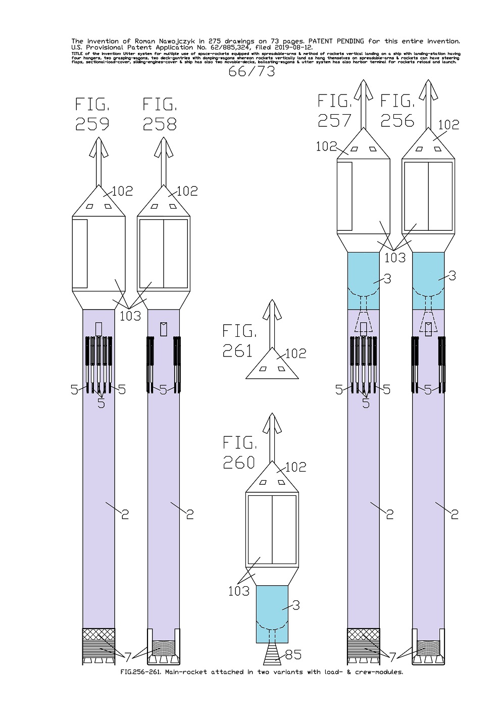
FIG.256, 257, 258, 259 show the views of the entire main-rocket 2 which is attached in two variants with a payload-module 103 and a crew-module 102 and which were not shown on any earlier views. The payload-module 103 has two gates with cargo bay while, the crew-module 102 has some windows. 
Here the main-rocket 2 is also equipped with ten spreadable-arms 5 so that this rocket with the current assemblage could land aboard the specific sea ship 10 with deck-mounted landing-station. 
Whereas FIG.256, 257 show the attaching variant wherein on the main-rocket 2 top is mounted the assemblage which consist of the second-stage-rocket 3 whereon is attached the payload-module 103 and whereto is attached the crew-module 102. 
Whereat FIG.256 is the side view, FIG.257 is the front view. This attaching variant will be applied while, on an Earth's low orbit this assemblage will separate from the main-rocket 2. Separating purpose can be that this assemblage will scheduled ascend toward the Earth's high orbit. Later this entire separated assemblage will be able to come back and dock to the same main-rocket 2 so that afterward together return on Earth. 
Whereas FIG.258, 259 show the attaching variant wherein on the main-rocket 2 top is mounted the assemblage which only consists of the payload-module 103 whereto is attached the crew-module 102. 

And FIG.258 is the side view, FIG.259 is the front view. Such attaching variant will be applied while, on the Earth's orbit this assemblage will not separate from the main-rocket 2. Consequently here is not the second-stage-rocket 3. 
FIG.260 is the side view of the separated assemblage which consist of the second-stage-rocket 3 with attached the payload-module 103 whereto is attached the crew-module 102. It is the same assemblage that is attached to main-rocket 2 on FIG.256, 257.
FIG.261 is the side view of the alone crew-module 102 which in such status would be used only for emergency separation from the assemblage and thus from the rocket. 
Purposes of the views on FIG.256-261 are presentations that the main-rocket 2 equipped with ten spreadable-arms 5 can have mounted on its top some various assemblages or modules and together with them can also land aboard the specific sea ship 10 that has deck-mounted landing-station. 
Shown here the attaching variants of the main-rocket 2 with the payload-module 103 and with the crew-module 102 enable the same possibilities of utilization as had earlier applied Space Shuttles. While, launching and vertical landing of shown here the main-rocket 2 with the assemblages are distinctly safer rather than of the Space Shuttles because situated on its top the crew-module 102 can whenever in emergency immediately separate from the assemblage by means of its peak-rocket-engines and later safely land on several parachutes. 


FIG.262-267 show examples of descending in the Earth's atmosphere of one booster-rocket 1 and of the main-rocket 2 with on its top mounted various assemblages and in various variants. These rockets descend in the Earth's atmosphere during the third so the last time period at slow speeds and therefor all rockets could already entirely lift upward their all spreadable-arms 5 and entirely deflected out their all steering flaps 6. Moreover all rockets still have totally shut down their sliding-engines-cover 7. On all rocket-frames the large arrows show their descent direction in the atmosphere. Whereat the external arrows show from what direction come flying atmospheric air. Therefore these arrows show in what way the air strongly crowds into all sub-assemblies, sections, assemblages and modules of these space-rockets. 
Whereas FIG.262, 263 show the side view and the top view of one booster-rocket 1 which has entirely lifted (spread out) its all six spreadable-arms 5. This booster-rocket 1 has not any attached module.
Whereas FIG.264, 265 show the side view and the top view of one main-rocket 2 which has entirely lifted (spread out) its all ten spreadable-arms 5. This main-rocket 2 has on its top directly attached the sectional-load-cover 4. 
This attaching and landing variant of the main-rocket 2 could be while, the second-stage-rocket 3 will remain on the Earth's orbit. This attaching and landing variant can also occur if the sectional-load-cover 4 is installed in different way, for example by some hinges to main-rocket 2. 

Whereas FIG.266 shows the side view of one main-rocket 2 which has also entirely lifted (spread out) all ten spreadable-arms 5. This view shows the attaching variant wherein on the main-rocket 2 top is mounted the assemblage that consist of the second-stage-rocket 3 with attached the sectional-load-cover 4. Here is visible that all cog-beams 93 are outside and on both sides of the second-stage-rocket 3. 
This attaching and landing variant of the main-rocket 2 will be while, the second-stage-rocket 3 will be taken back from the Earth's orbit. 
And this attaching and landing variant causes that inside the sectional-load-cover 4 can be some load taken back from the Earth's orbit. For example, a large satellite taken back for repair.


Whereas FIG.267 shows the side view of one main-rocket 2 which has also entirely lifted (spread out) all ten spreadable-arms 5. The view shows the attaching variant wherein on the main-rocket 2 top is mounted the assemblage that consist of the second-stage-rocket 3 with attached the payload-module 103 and the crew-module 102. 
This attaching variant of the main-rocket 2 will be while, the second-stage-rocket 3 will be taken back from the Earth's orbit with attached the payload-module 103 and the crew-module 102. 
This attaching and landing variant causes that inside the payload-module 103 can be some load taken back from the orbit.


FIG.268, 269 show the front views of one main-rocket 2 which is joined on both sides with two booster-rockets 1. 
And FIG.268 is the diminished front view of three joined space-rockets. 
And FIG.269 is the enlarged front view of the upper parts of the same three joined space-rockets which are on FIG.268. On the main-rocket 2 top is mounted the assemblage which consist of the second-stage-rocket 3 with attached the sectional-load-cover 4. 

Whereat the sectional-load-cover 4 is directly attached to second-stage-rocket 3 and is attached to main-rocket 2 by means of the cog-beams 93. 
And inside the sectional-load-cover 4 is fastened some
payload which will be carried out on the Earth's orbit. In such status and arrangement these three joined space-rockets are entirely ready for launch toward space. 
These views target presentation that the spreadable-arms 5 fastened to main-rocket 2 and to two booster-rockets 1 do not hinder joining them with themselves. These three rockets are joined with themselves by means of some foldable crossbars without any numbers. 


FIG.273 is prospectus presentation which shows for example several drawing statuses of one main-rocket 2 which lifted-off and its further traveling trajectory while, unexpectedly happened failure of some main engine. 
The current whole presentation shows process of this entire rocket salvation and its emergency landing aboard the specific sea ship 10 at open sea. 
On the rocket drawing statuses and alongside the arrows show the directions of its traveling trajectory. The exhaust-fumes 9 gush down of all rocket main engines in actual statuses. 
At beginning this main-rocket 2 is in three statuses in front drawings. Shortly after the rocket liftoff happens failure of some main engine and this engine stalled. It is visible on this rocket second drawing status and it is indicated with the large exclamatory sign. Consequently this main-rocket 2 became forced to emergency landing. Without full powers of all main engines, this main-rocket 2 will not be able to ascend upward to intended Earth's orbit. If this rocket had not landing possibility on the spreadable-arms 5 ergo at this juncture the entire rocket with
payload would be totally lost. 
Despite failure of some main engine, this main-rocket 2 can maintain its vertical position and its height above sea-water. Thereby it is probable that this rocket will be able to travel "rocketly" and get through up to specific sea ship 10 in order to land on it. 

Thereafter all rocket statuses are in the side drawings and show the main-rocket 2 travel toward the specific sea ship 10. 
Because this specific sea ship 10 is very remote at open sea, therefor this main-rocket 2 must travel until the specific sea ship 10 - likely in vertical position. 
Shortly before vertical landing aboard the specific sea ship 10, this main-rocket 2 lifts upward its all ten spreadable-arms 5 in order to hang up itself on two large damping-wagons 31 on the specific sea ship 10. 
The current whole view target presentation that every rocket equipped with spreadable-arms 5 can in emergency land aboard the specific sea ship 10. As result of such method, in some circumstances there is possible total salvage of the main-rocket 2 together with the second-stage-rocket 3 and the
payload 100 in the sectional-load-cover 4. Consequently it is obvious that such total salvage of the rocket after some failures will provide giant economic profit. Furthermore after replacing of a damaged main engine the same space-rocket can very quickly again be launch toward space. Therefor it will cause very short time delay in dispatch of the same payload into orbit. 
Nowadays, such total salvage of the rocket with the
payload after some failures is not possible with any other methods of the space-rockets launching. At present almost all failures of the space-rockets causes their total wastage and it results in giant economic loss. Furthermore it result in very long-lasting delay in renewed dispatch of the same payloads to Earth's orbit because the same payloads must be anew manufactured. 


The views on FIG.274, 275 show for example one booster-rocket 1 which slips by through the wide-opened interior of the specific sea ship 10 at open sea. And FIG.274 is the side view, FIG.275 is the top view. 
According to plan, this booster-rocket 1 was supposed to land on this specific sea ship 10. However during this rockets descent happened some failure of the main engines which were supposed to bring total stop of the rocket descent and make possible landing aboard the specific sea ship 10. In order to prevent any strike of this rocket onto specific sea ship 10 there were quick and entirely spread apart in two directions both movable-decks 15. Both 
movable ship-gantries 20 were already earlier entirely spread apart in two directions of the specific sea ship 10. 

As result, inside the specific sea ship 10 multi-hull arose the giant open interior where-into is only sea surface. Accurately into this giant open interior struck hard this booster-rocket 1 and plunged in sea-water. 
Therefore, this booster-rocket 1 did not strike into any member of the specific sea ship 10. This rocket became lost but the entire specific sea ship 10 survived and that is giant economic profit. Moreover this specific sea ship 10 and the landing-station are immediately ready for landing the next space-rocket, because there will only be enough to push together both movable-decks 15. 
On the views are distinctly visible water splashes which arose after the rocket stroke onto sea surface. 

.


THE END