I am Master Mariner of the Maritime University in Poland.
I reside in Älmhult, Sweden

|
Welcome everybody, RoNawo.com is an information website of the engineer and inventor Roman Nawojczyk. This website endeavours to show up my splendit invention with the granted patent.
The patent for this my entire invention is granted ! The patent has a number US 11 932 424 and is vissible on the US Patent and Trademark Office website.
Search on https://ppubs.uspto.gov/pubwebapp/static/pages/landing.html take Advanced Search and write in the patent number 11932424.
The patent grant in pdf. can be seen here.
The alone patent in pdf. can be seen here.
My other approx. 20 inventions I will show up in the future.
|
|
I am Master Mariner of the Maritime University in Poland.
I reside in Älmhult, Sweden
|
|
|
.
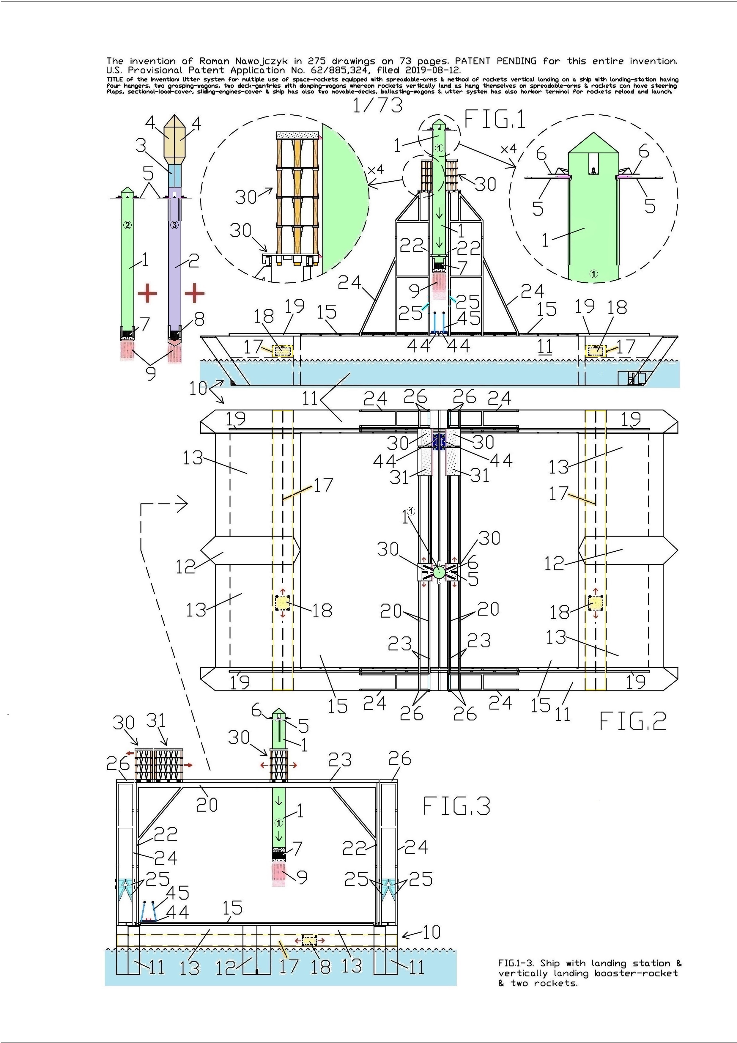
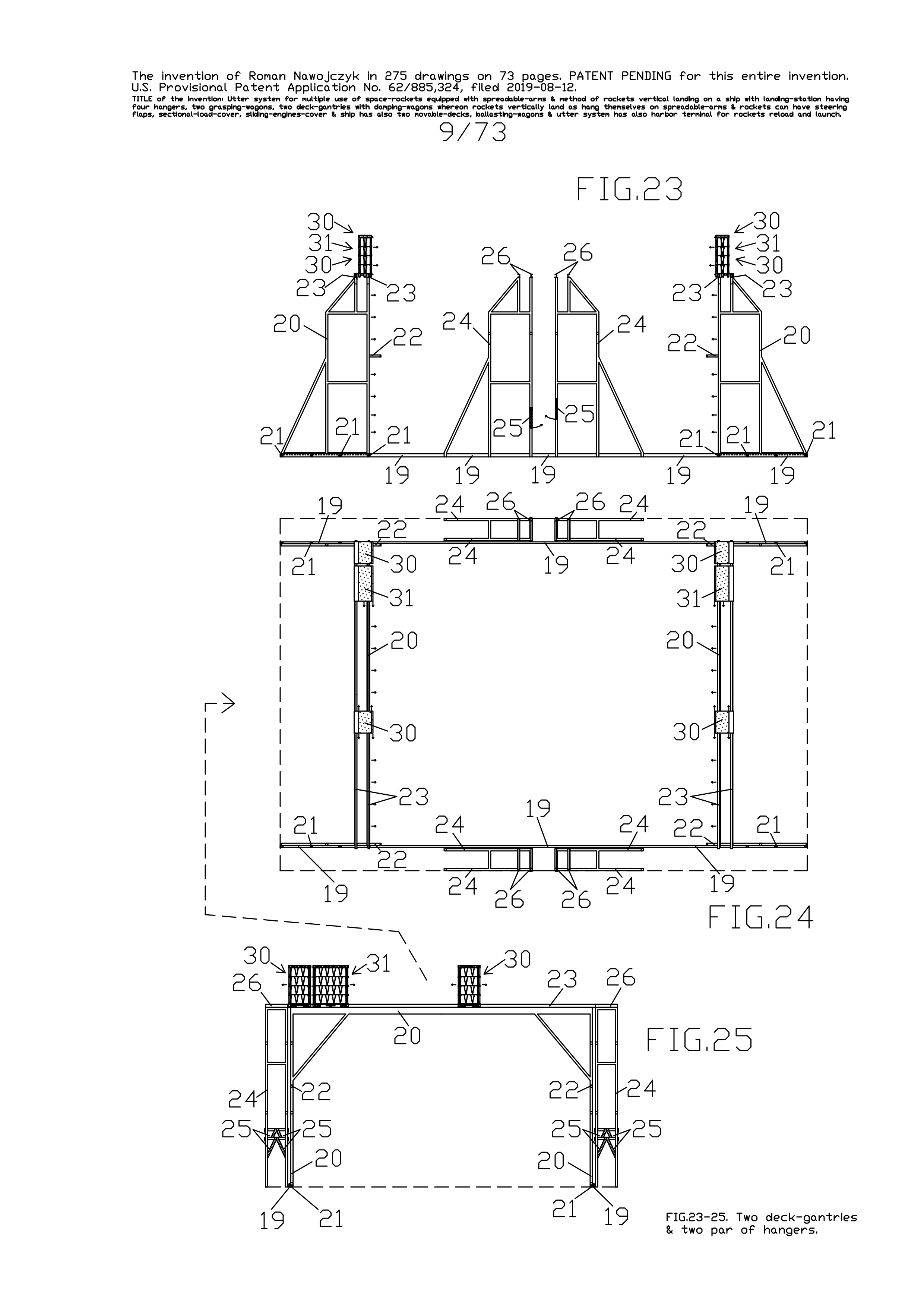
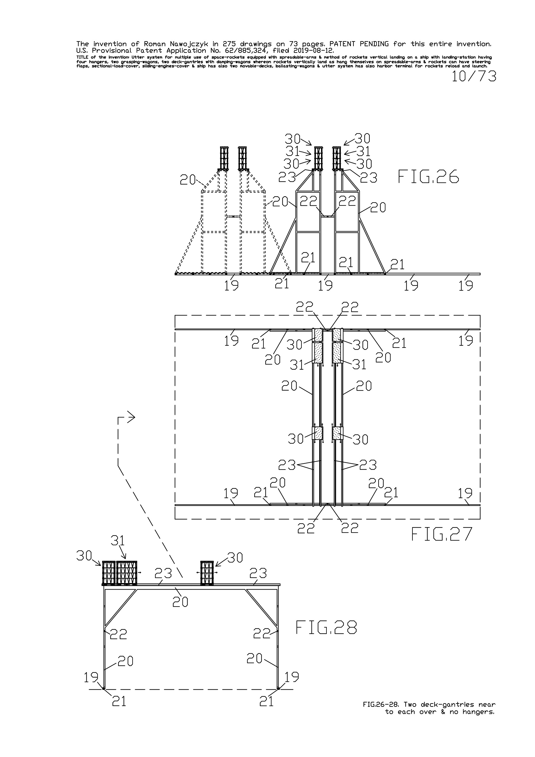
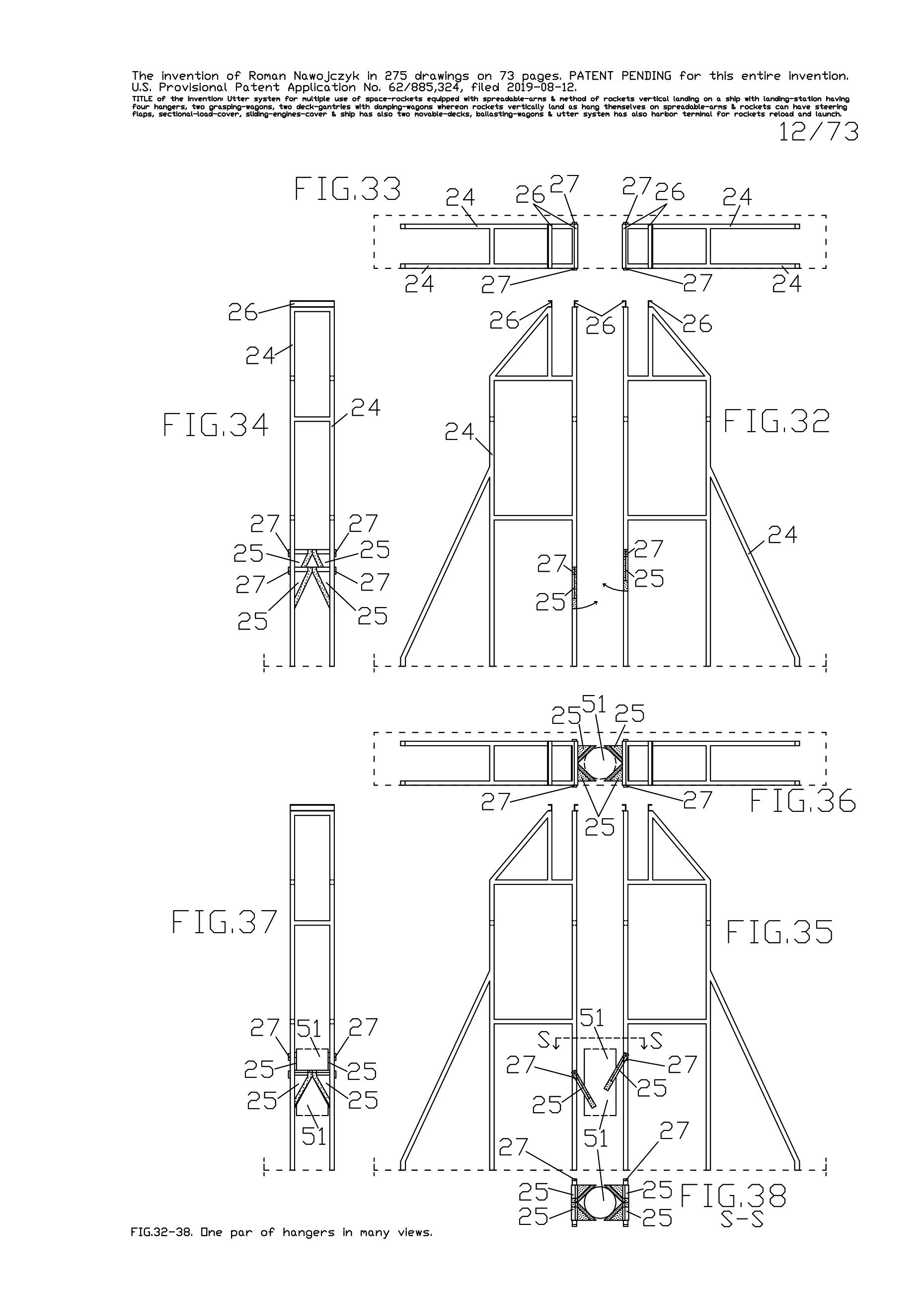
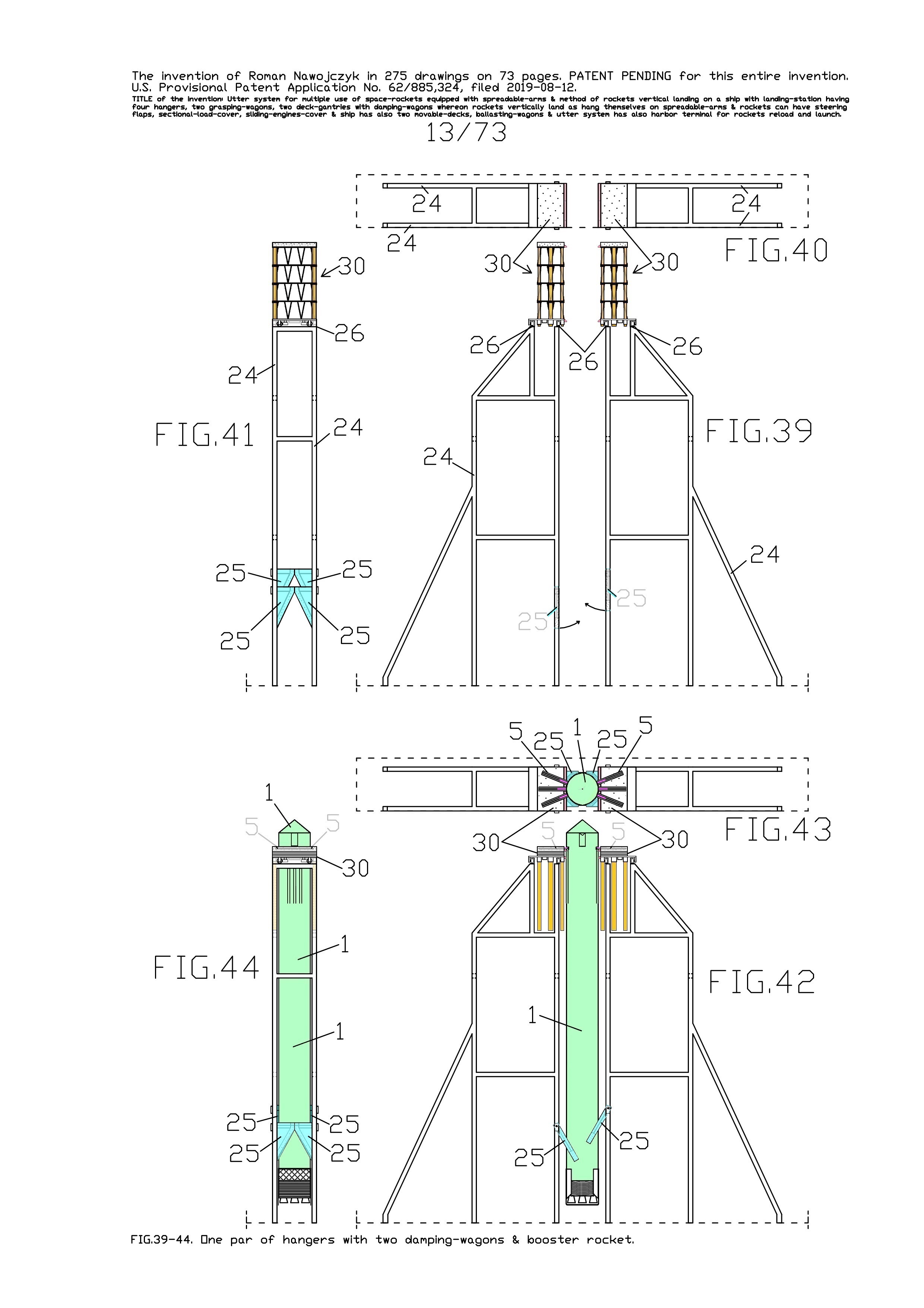
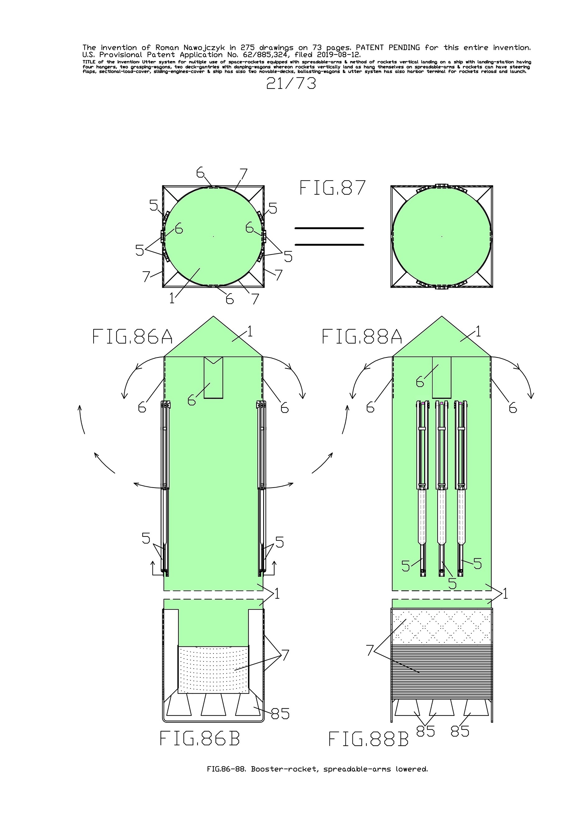
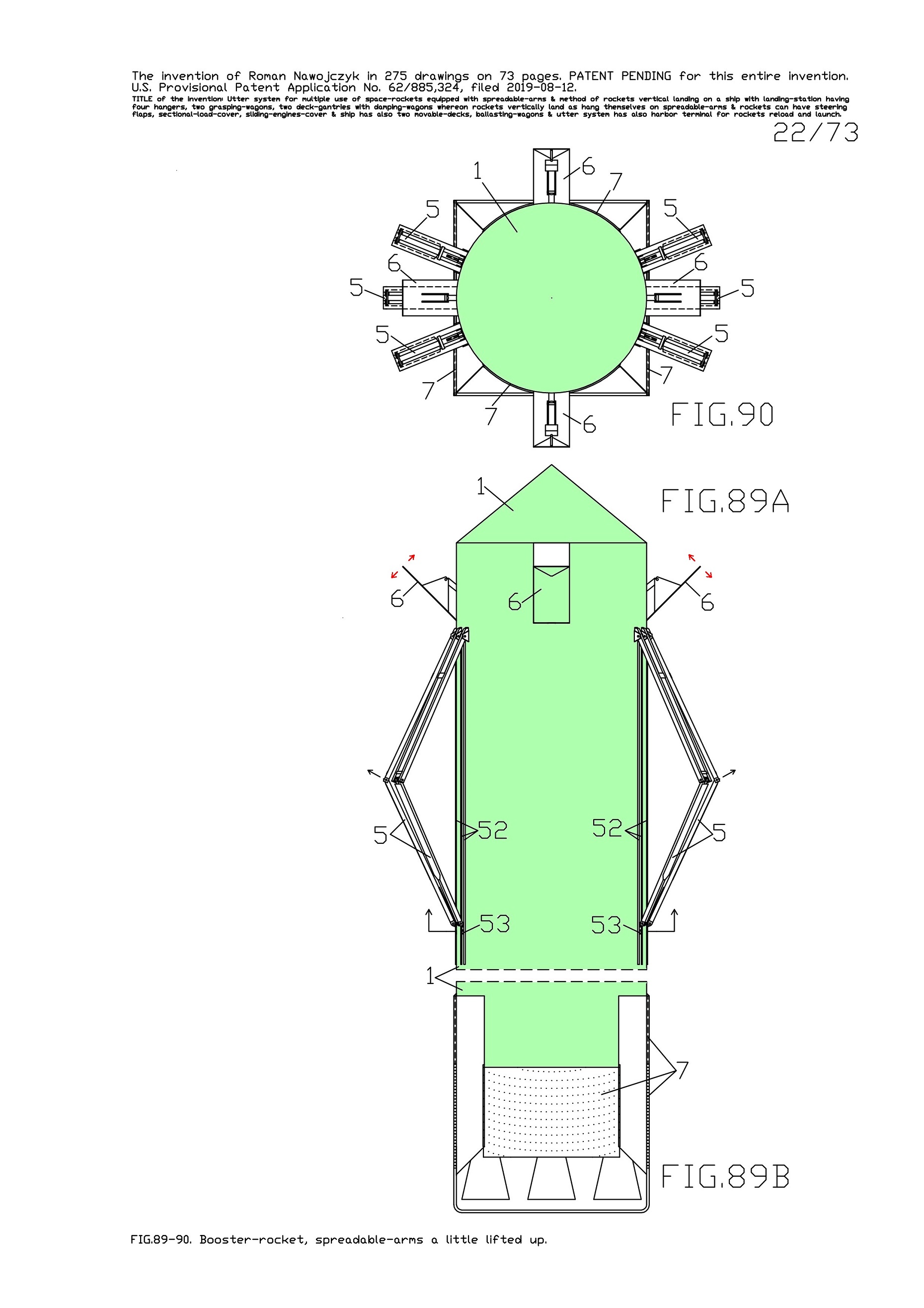
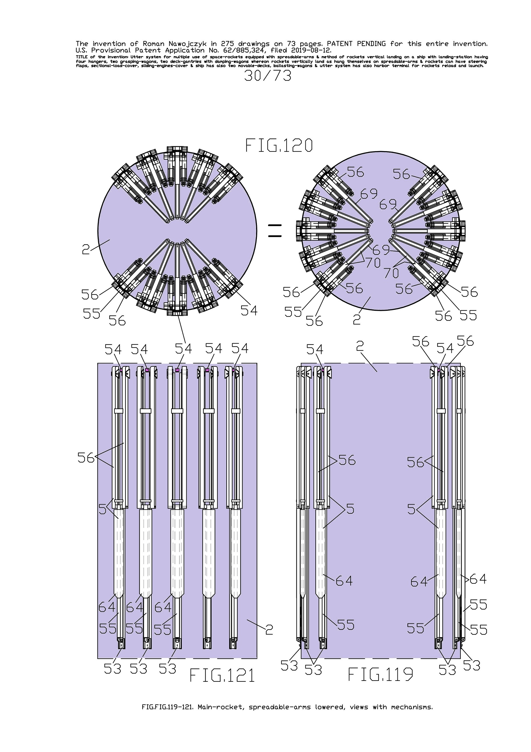
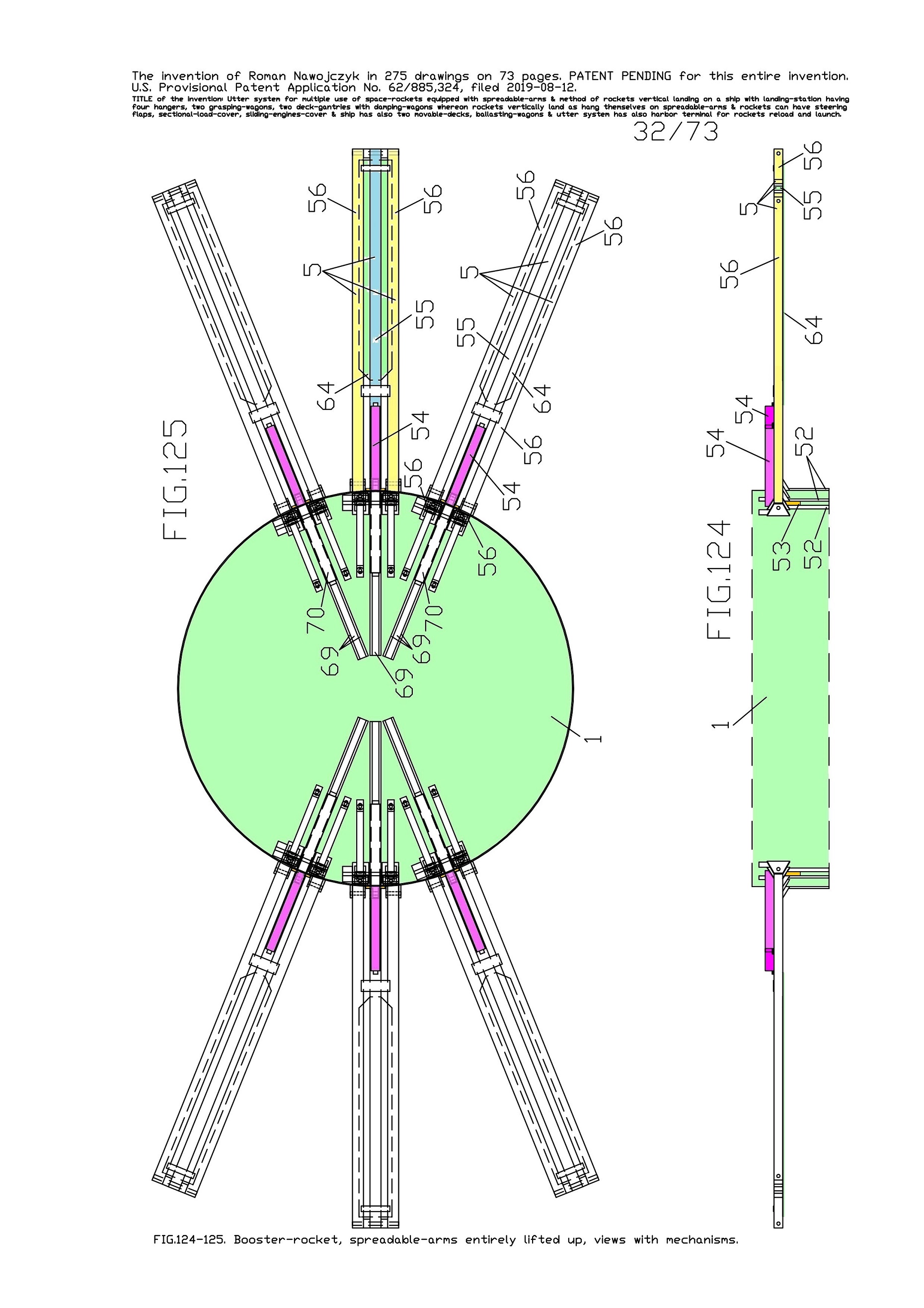
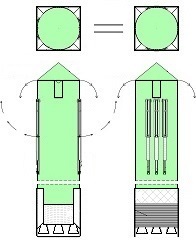
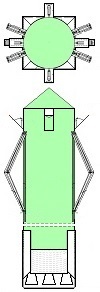
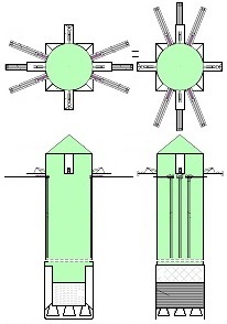
Space-rockets equipped with spreadable-arms and a System for them.
Everything invented by Roman Nawojczyk.
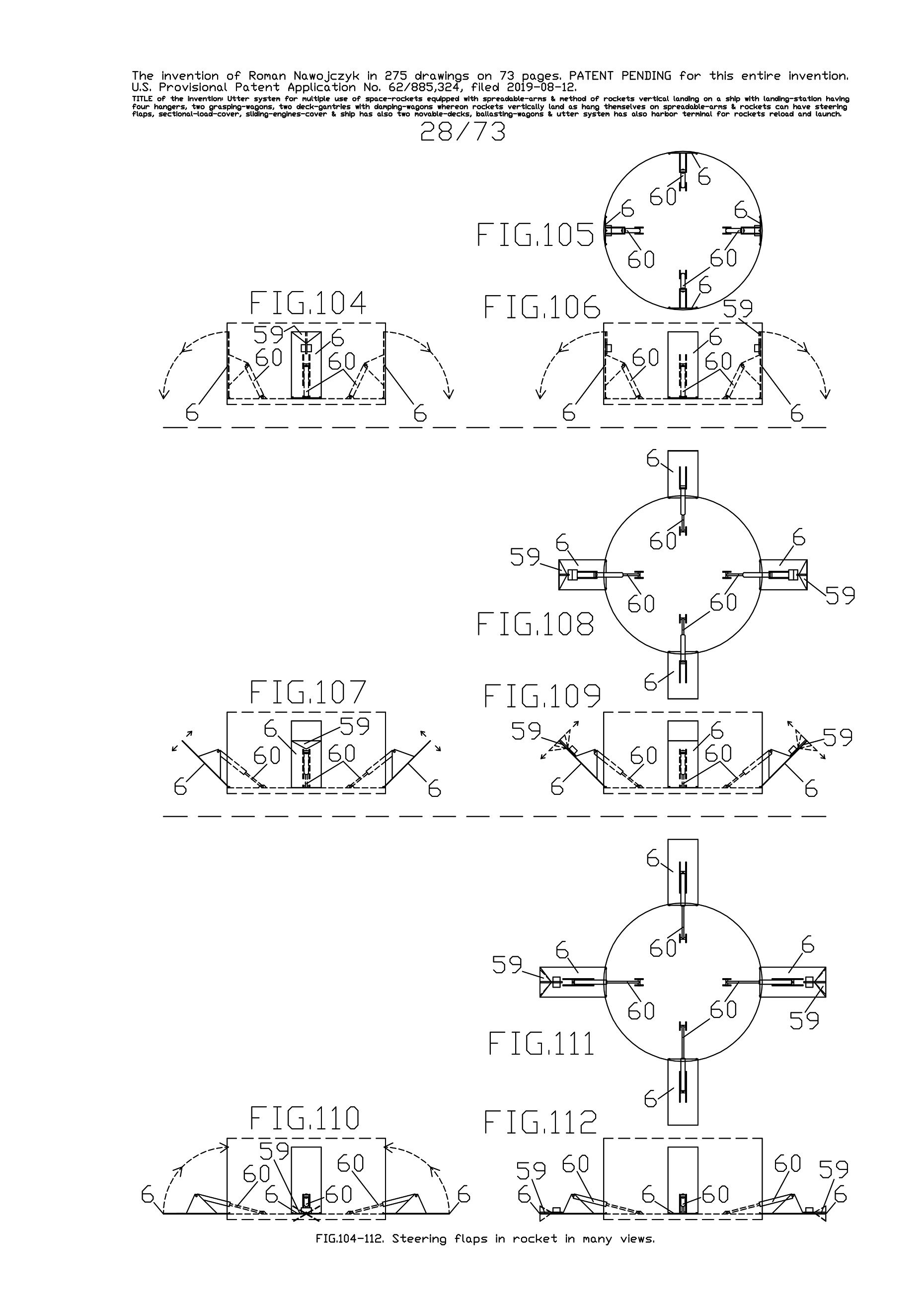
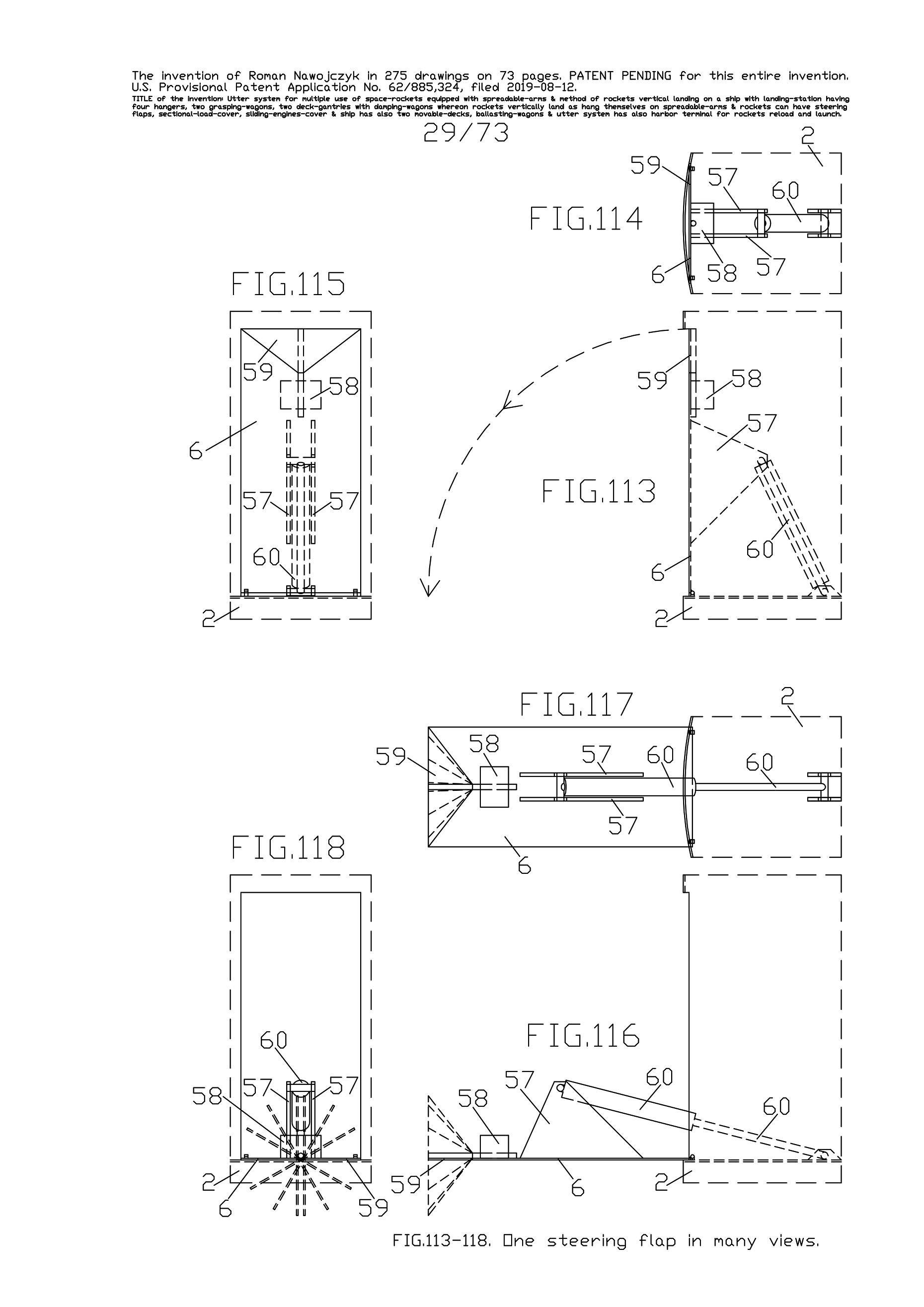
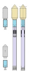
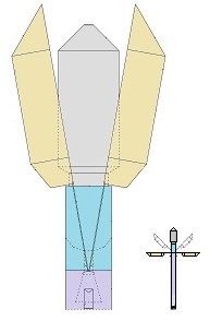
For these space-rockets I also invented steering flaps,
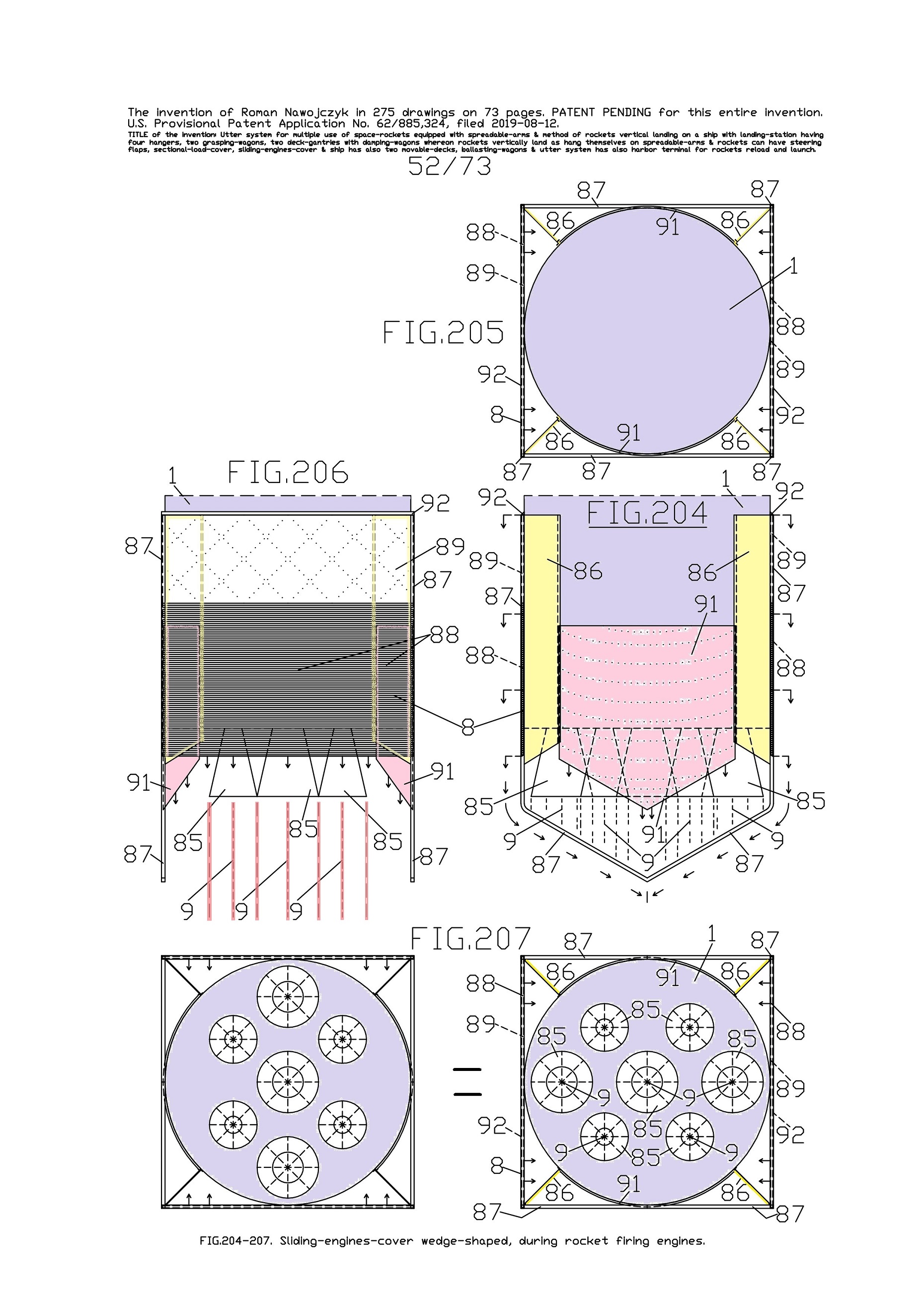
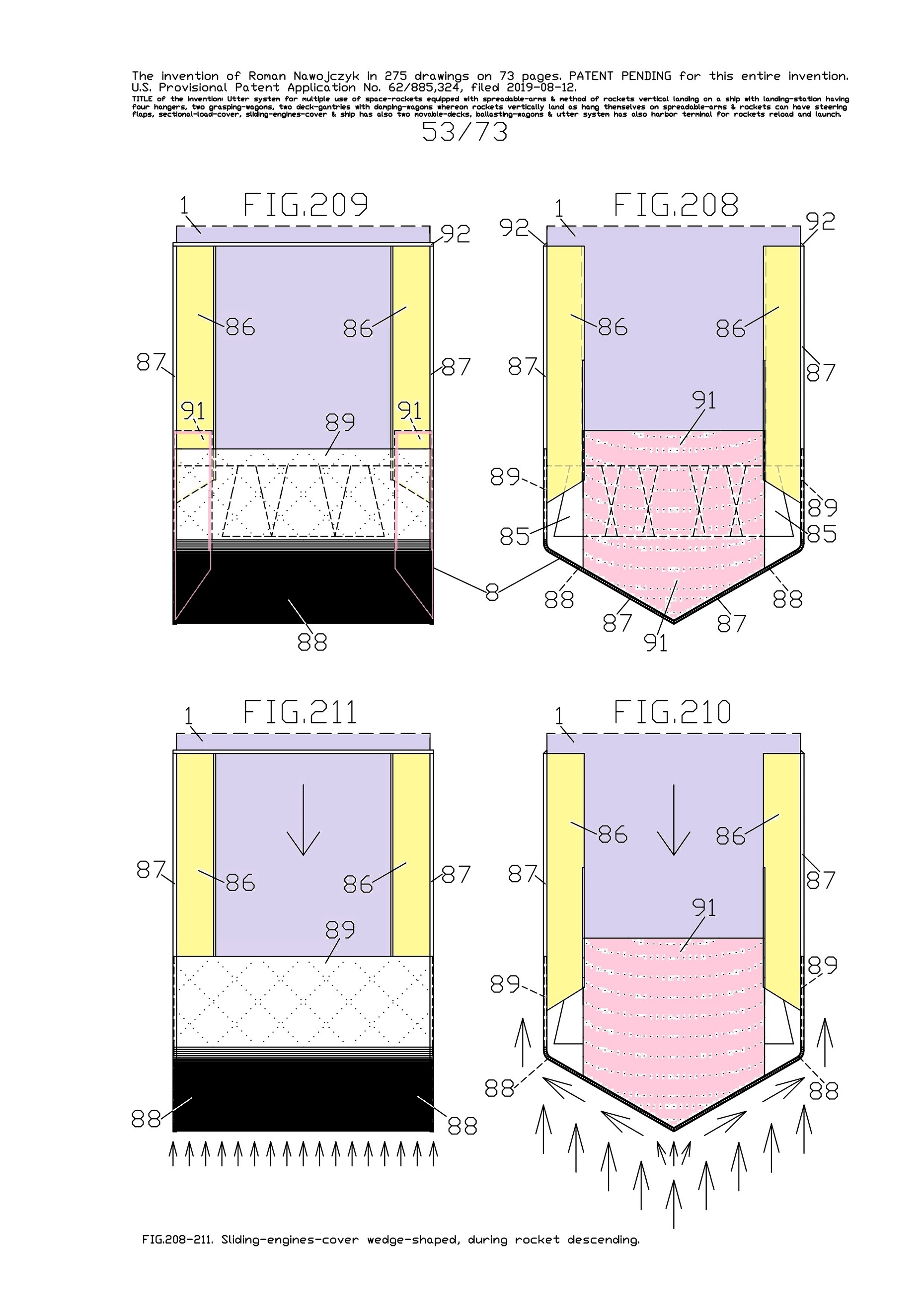
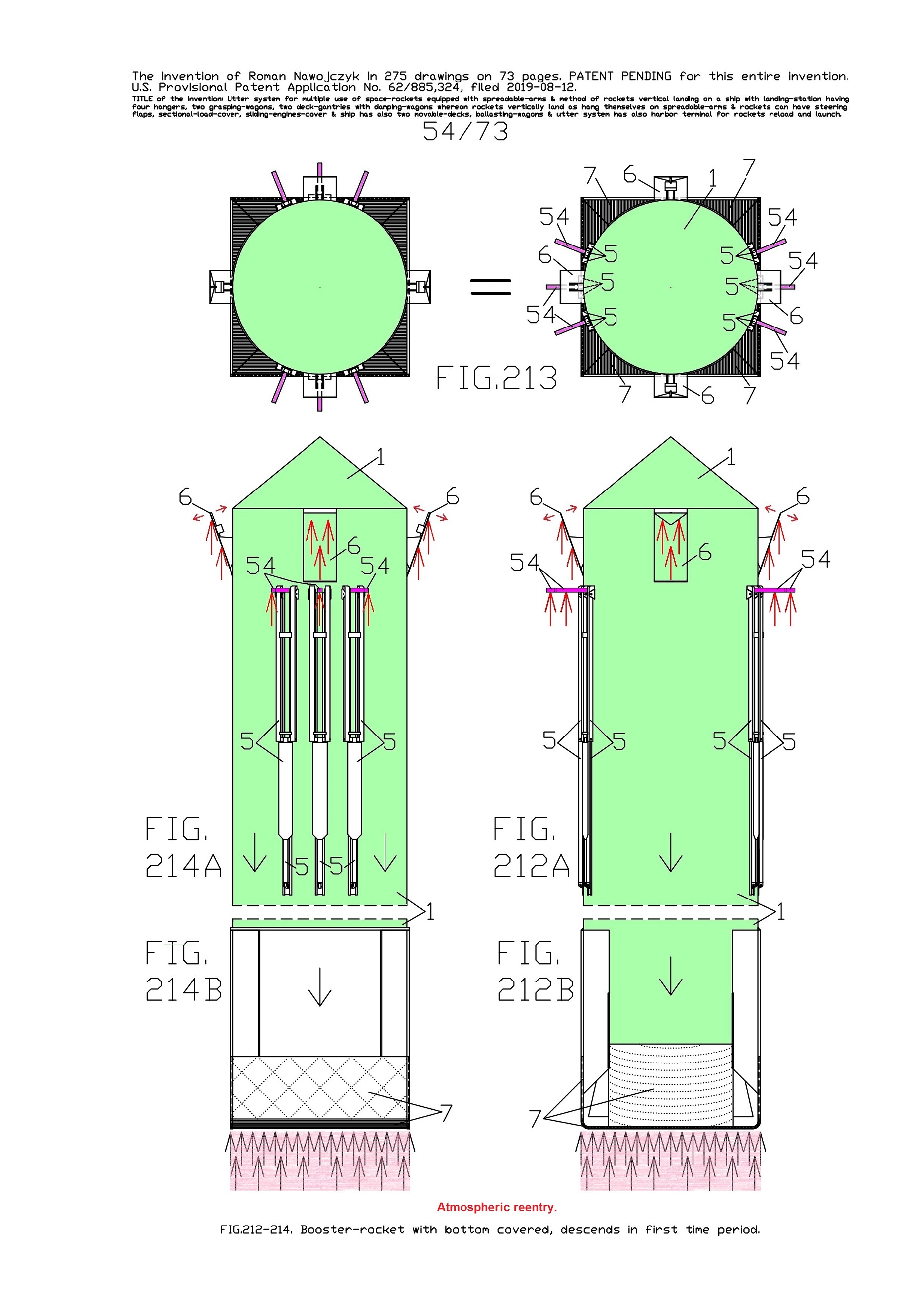
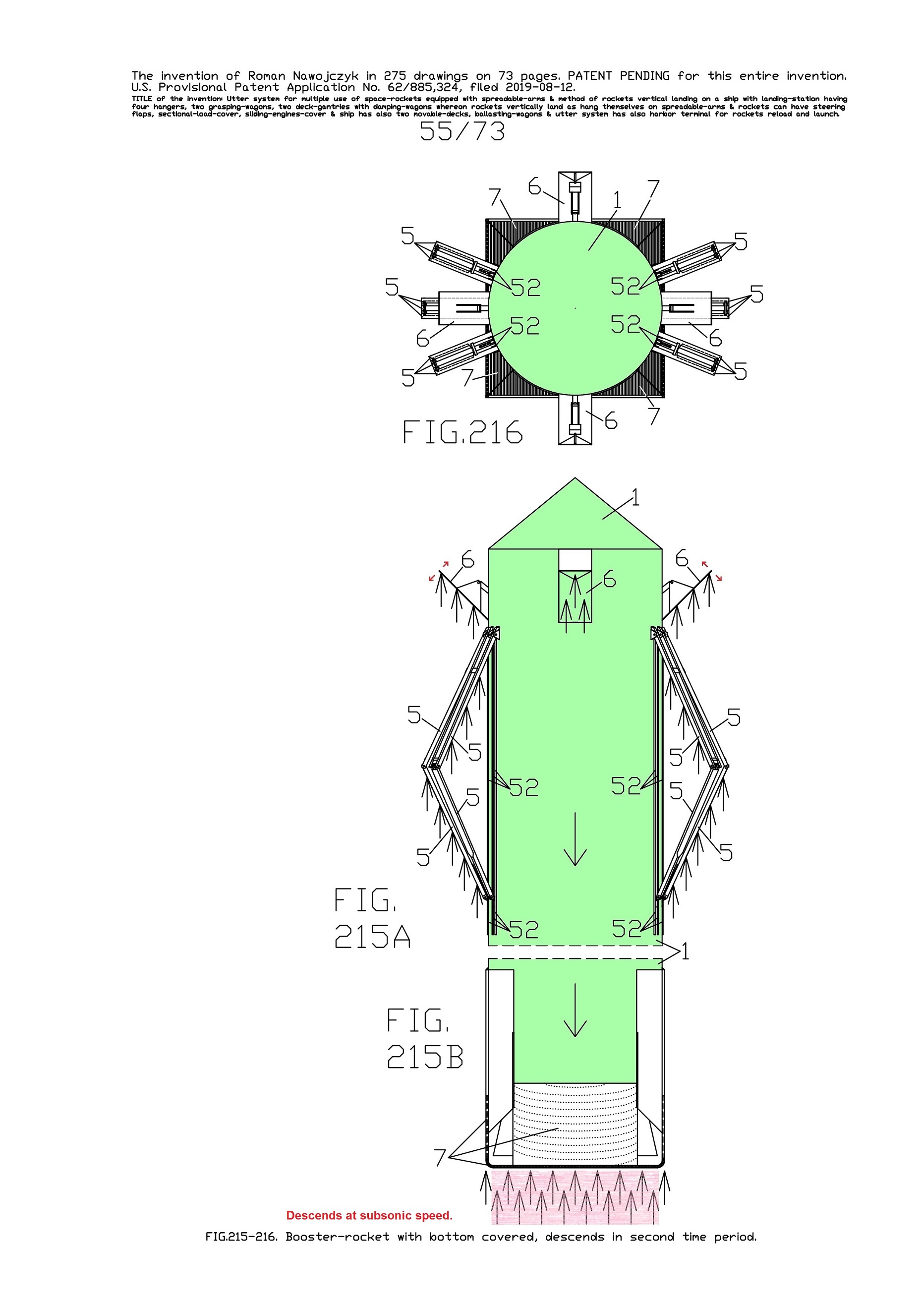
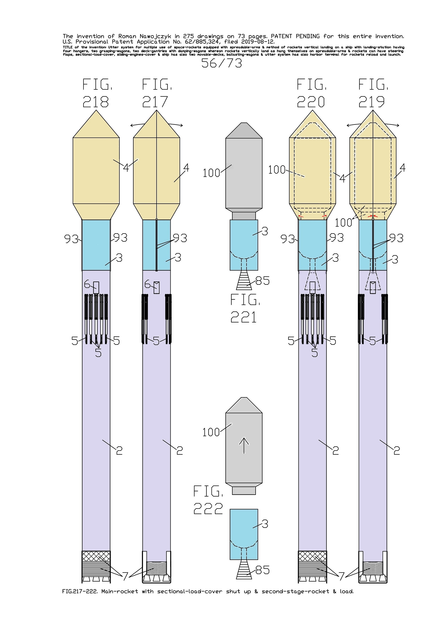
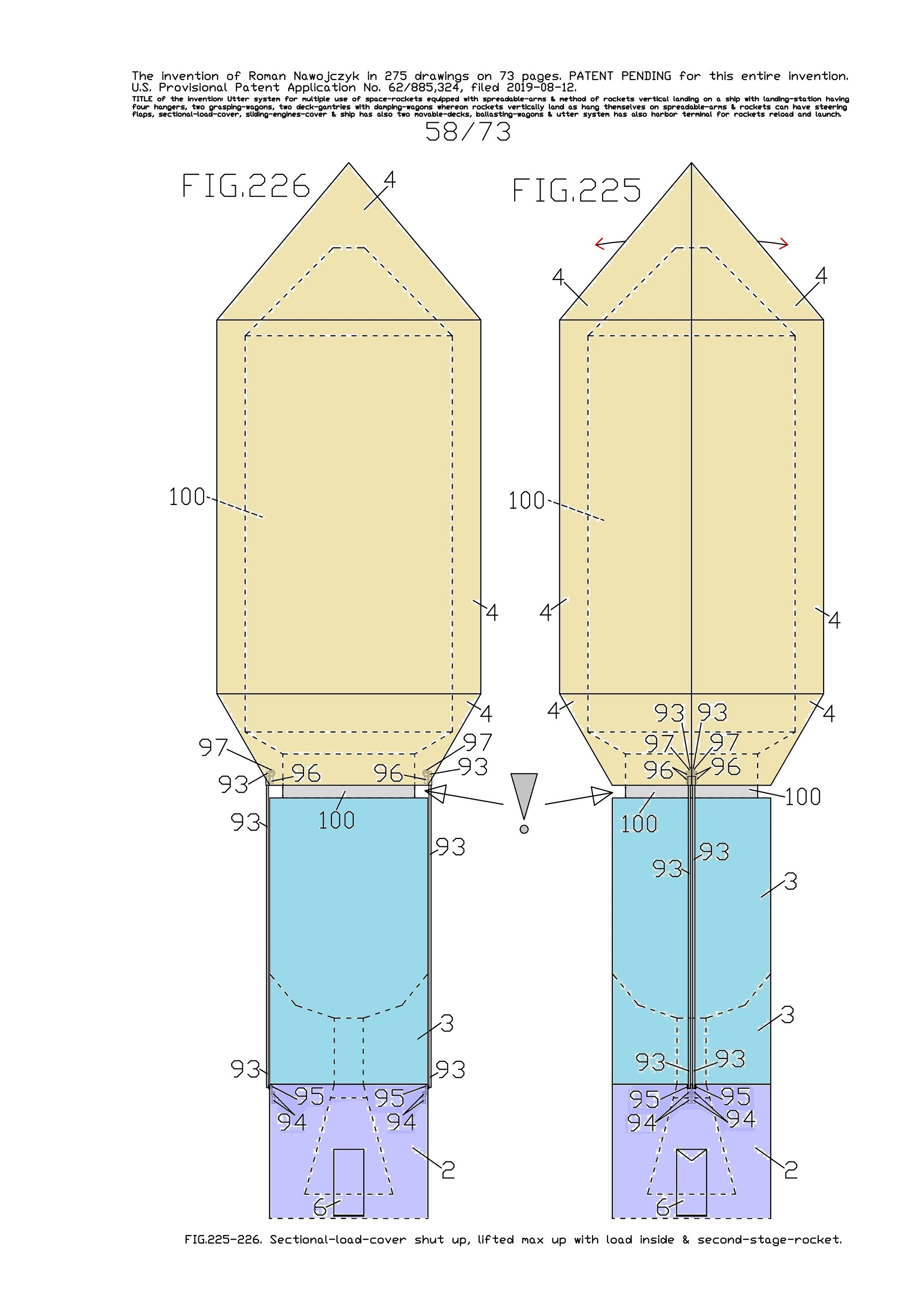
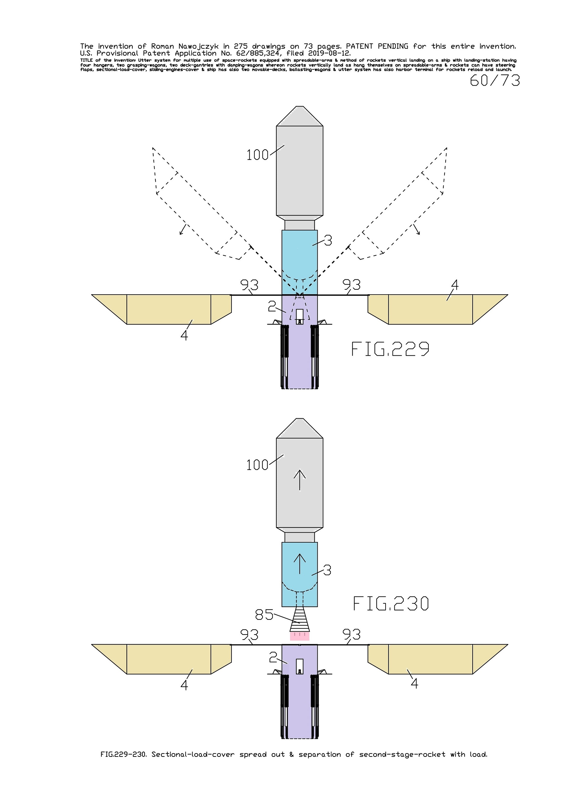
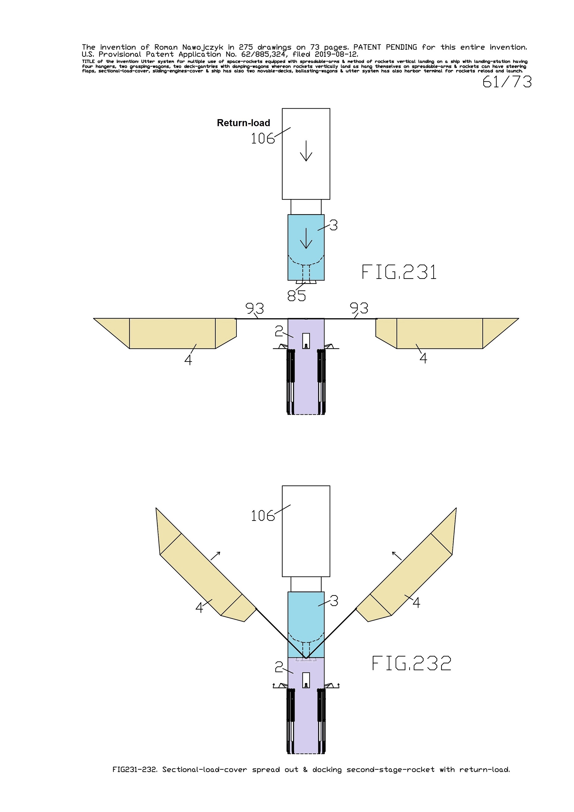
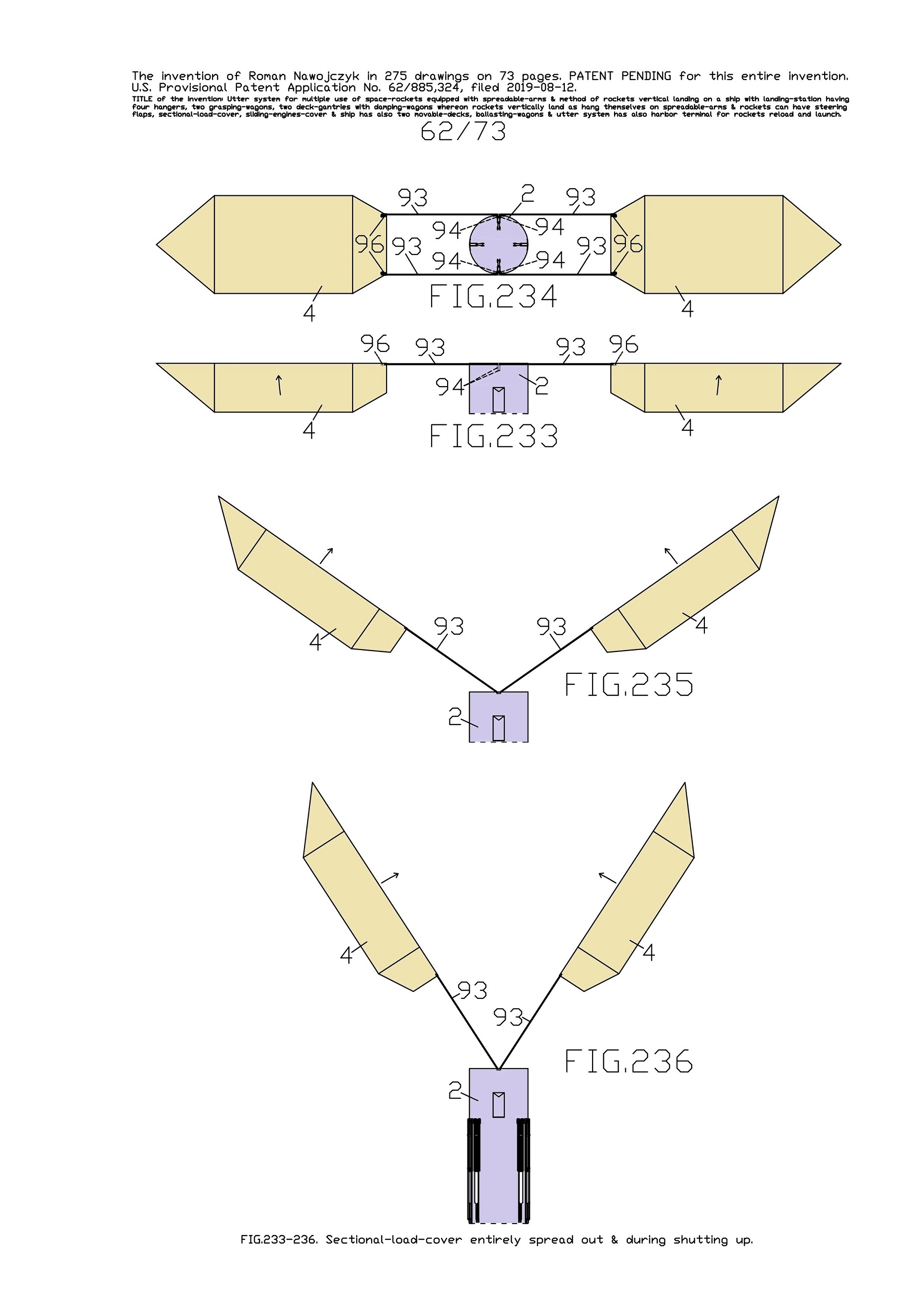
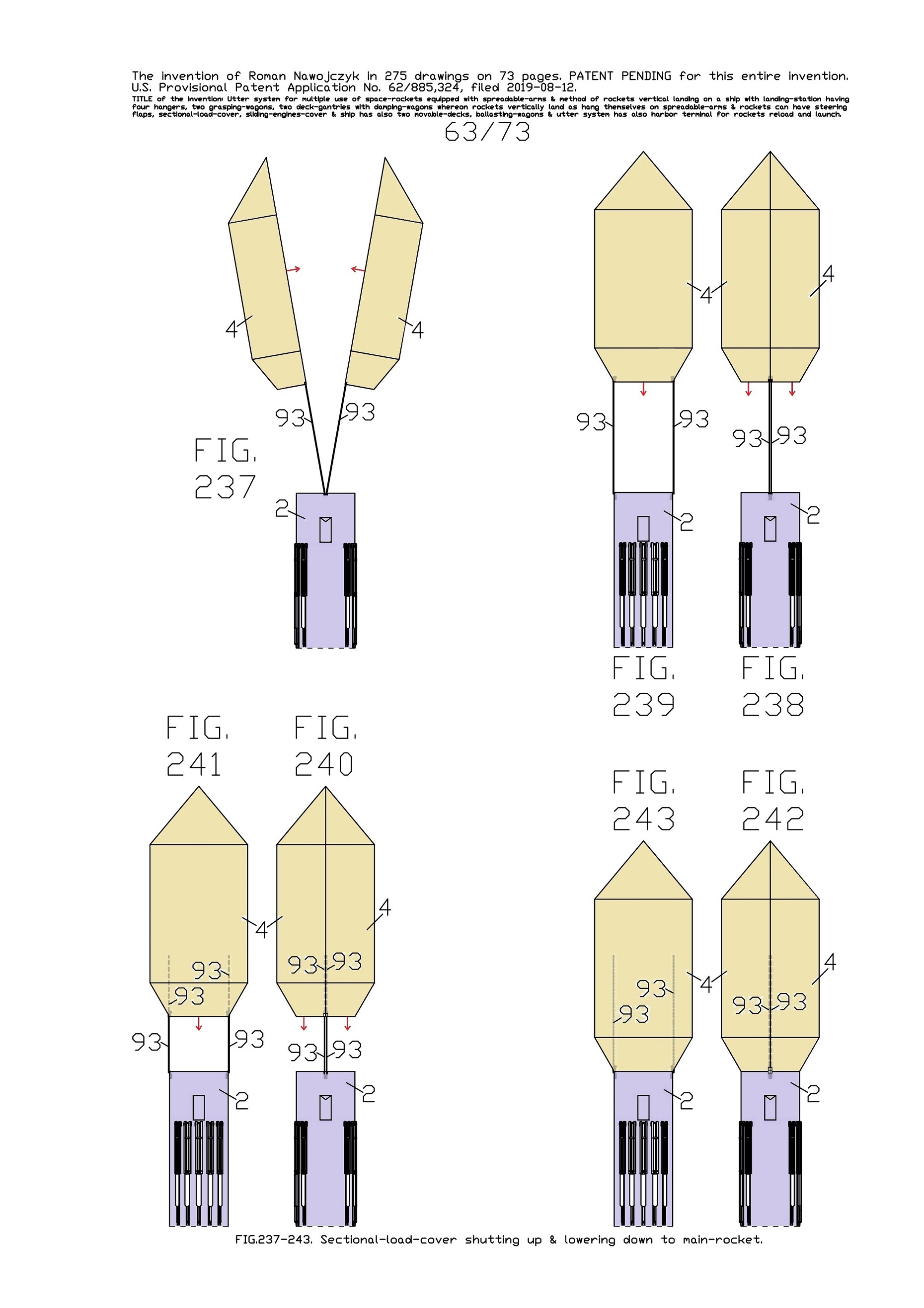
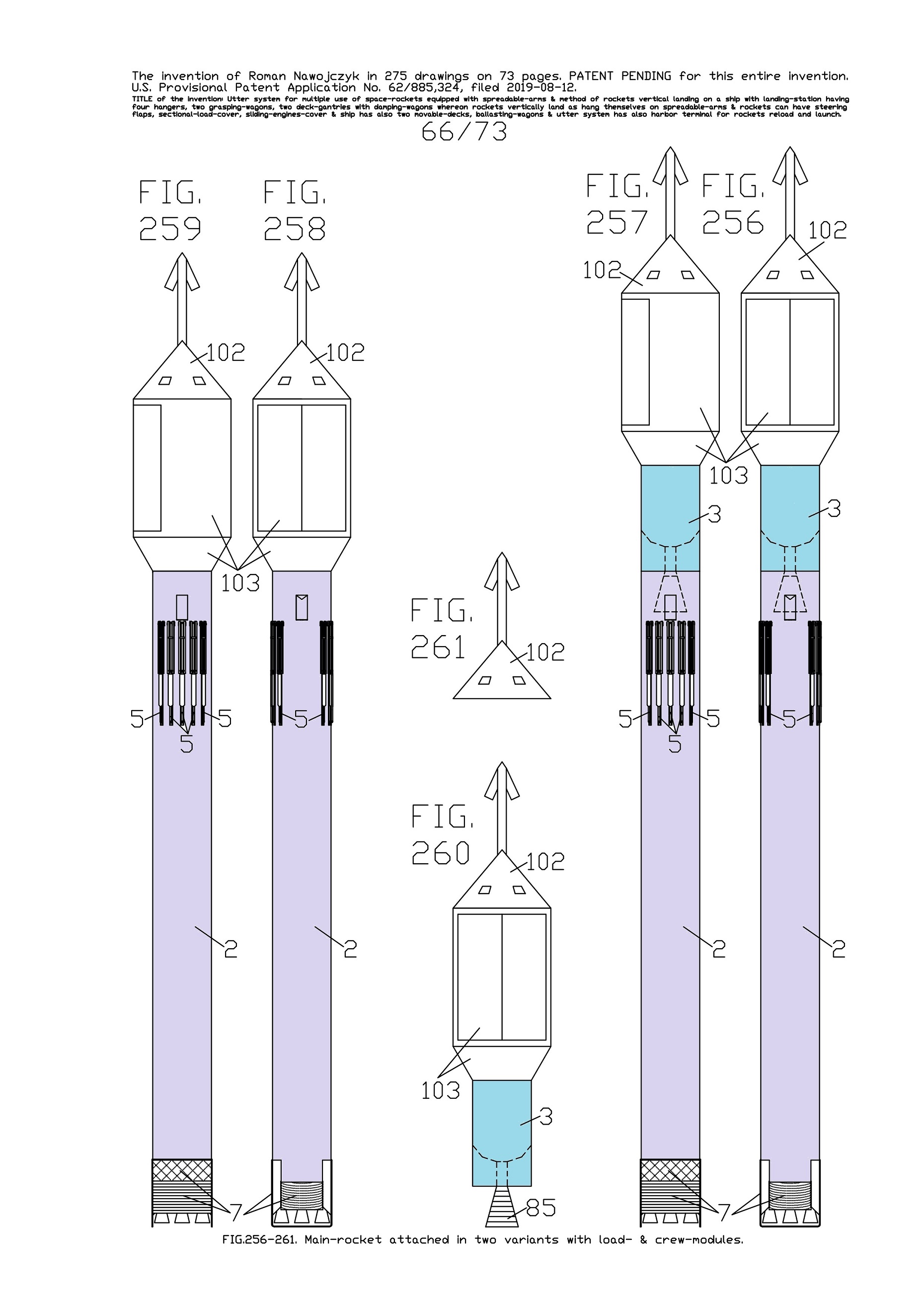
a dividable sectional-load-cover and a sliding-engines-cover (having jalousies).
As result these space-rockets are totally reusable whereas not any company has suchlike.
|


|
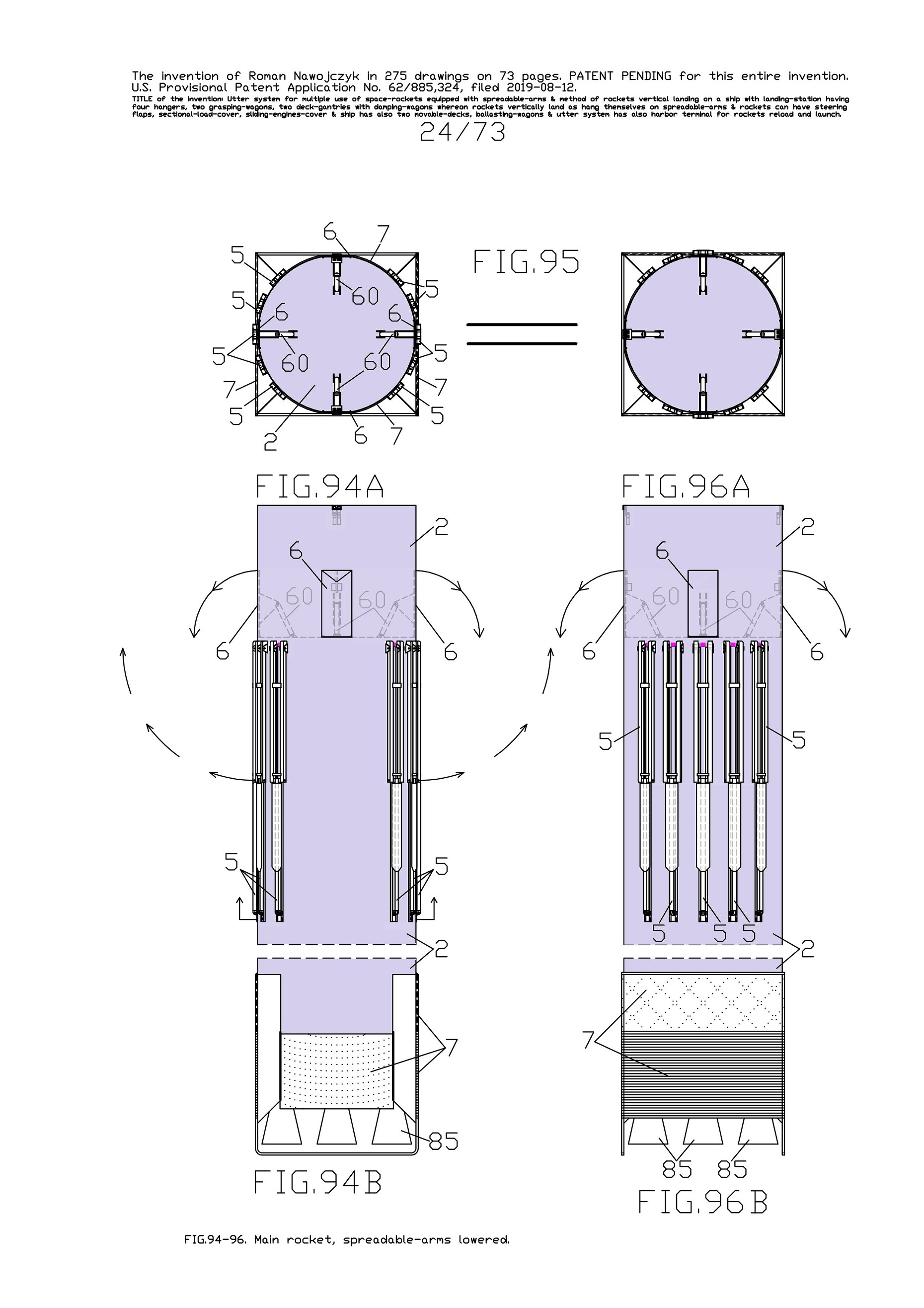
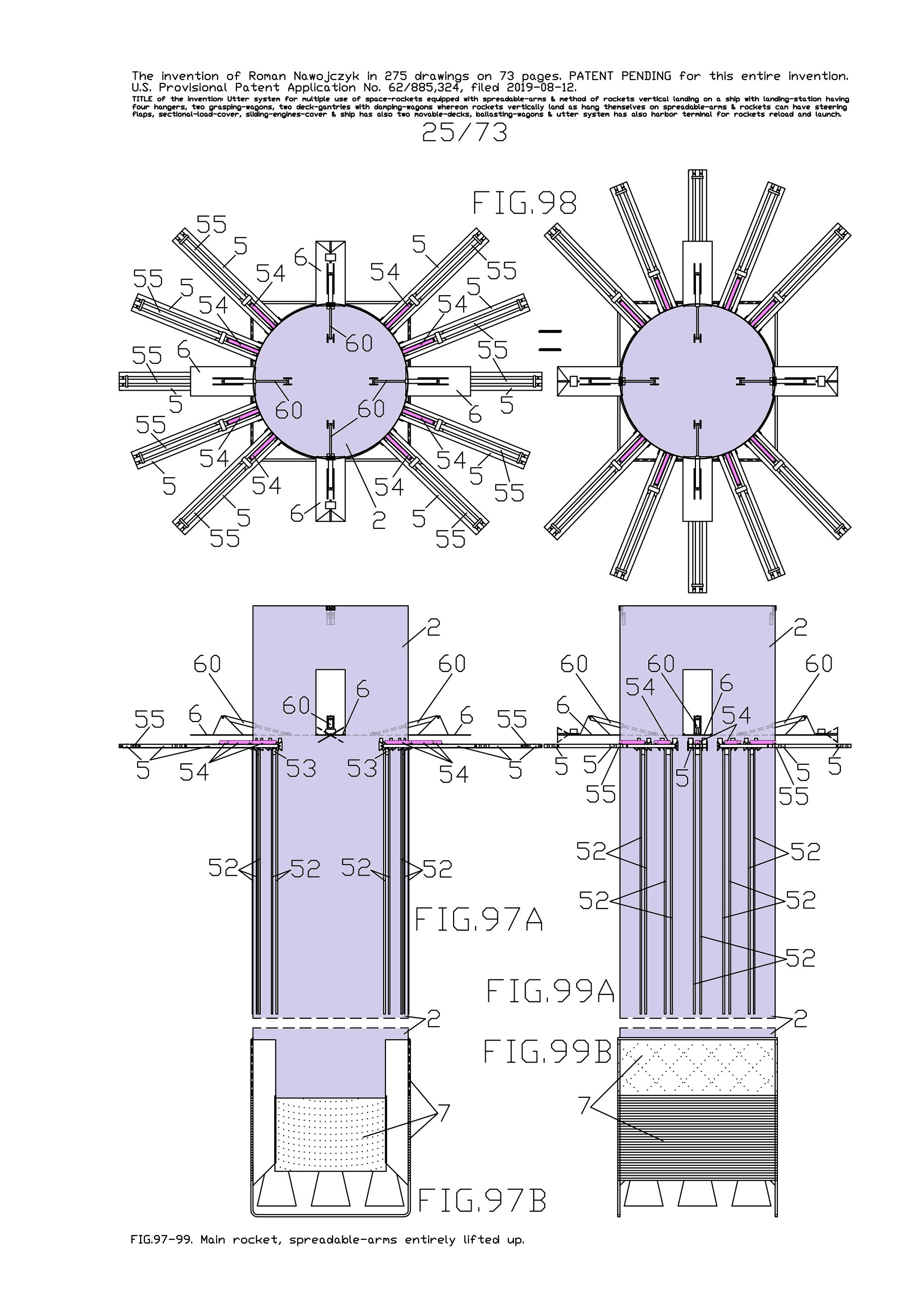
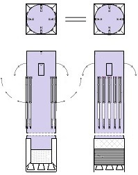
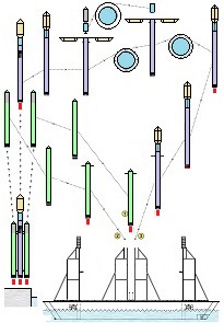
Thus now, I would like to depict my great invention for the space industry. It is the System for space-rockets equipped with several spreadable-arms. It sometimes allows landing together with second stage rocket and large return-load (e.g., satellite). And furthermore it is perfectly suitable for the space-rocket launches with astronauts because the space-rocket landings are super safe ! ! !
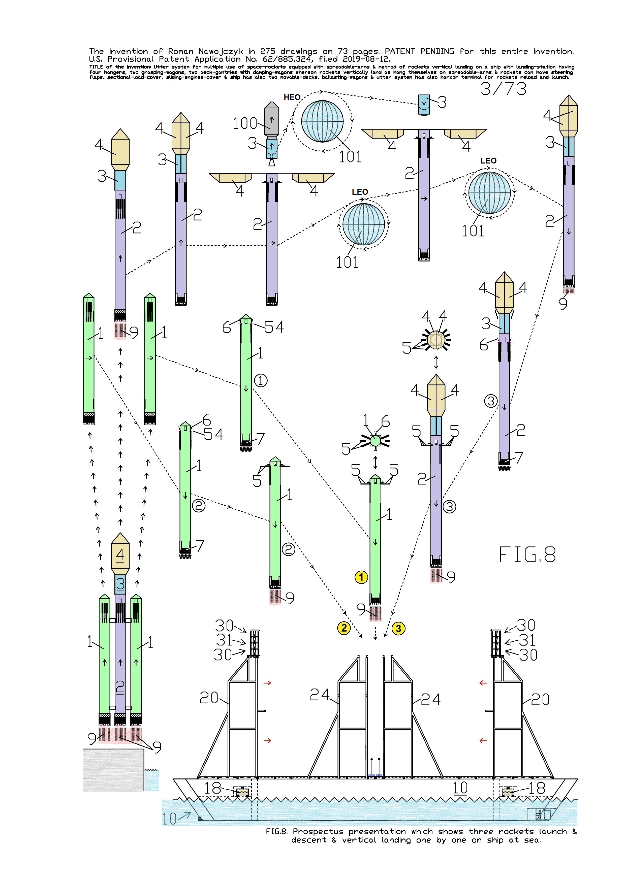
I am absolutely certain that my System is very needed for military and private sector because it's very good, economic, develop-able, safe and for rapid multiple use. My System is very advance, elaborated and is much better than all other space-rocket launching and landing methods ! ! ! My System is fully available on this website and is presented on hundreds precise drawings with extensive descriptions. In this System, the space-rockets lift-off from the spreadable-arms and land on them. Therefore, my System creates several new possibilities that were not possible before. For example - launching several permanently joined space-rockets in a row and later landing together. My System is so good that allows to build ONLY ONE first stage space-rocket and several second stages and use them endlessly, e.g., two times each day ! ! ! This System includes This System
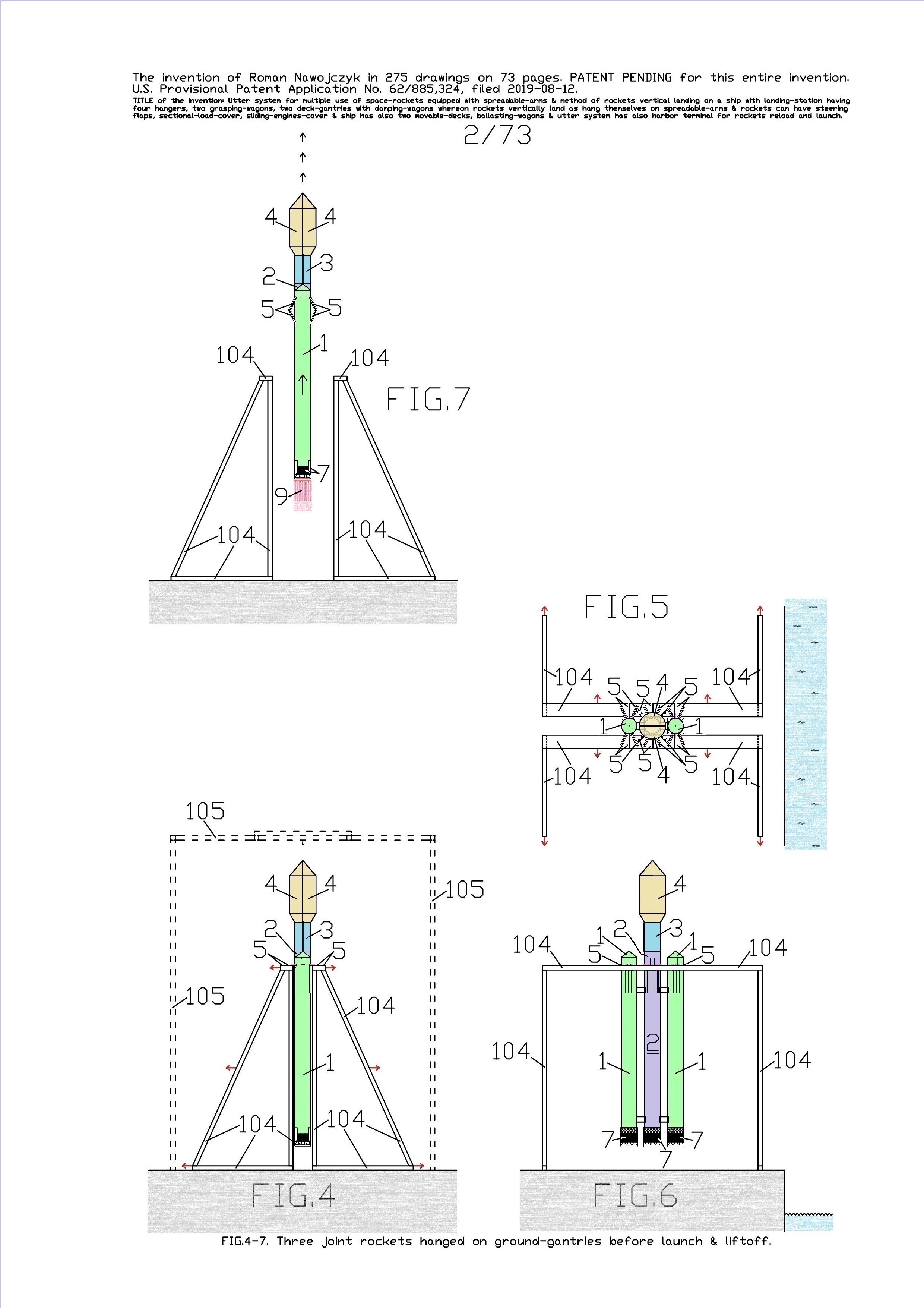
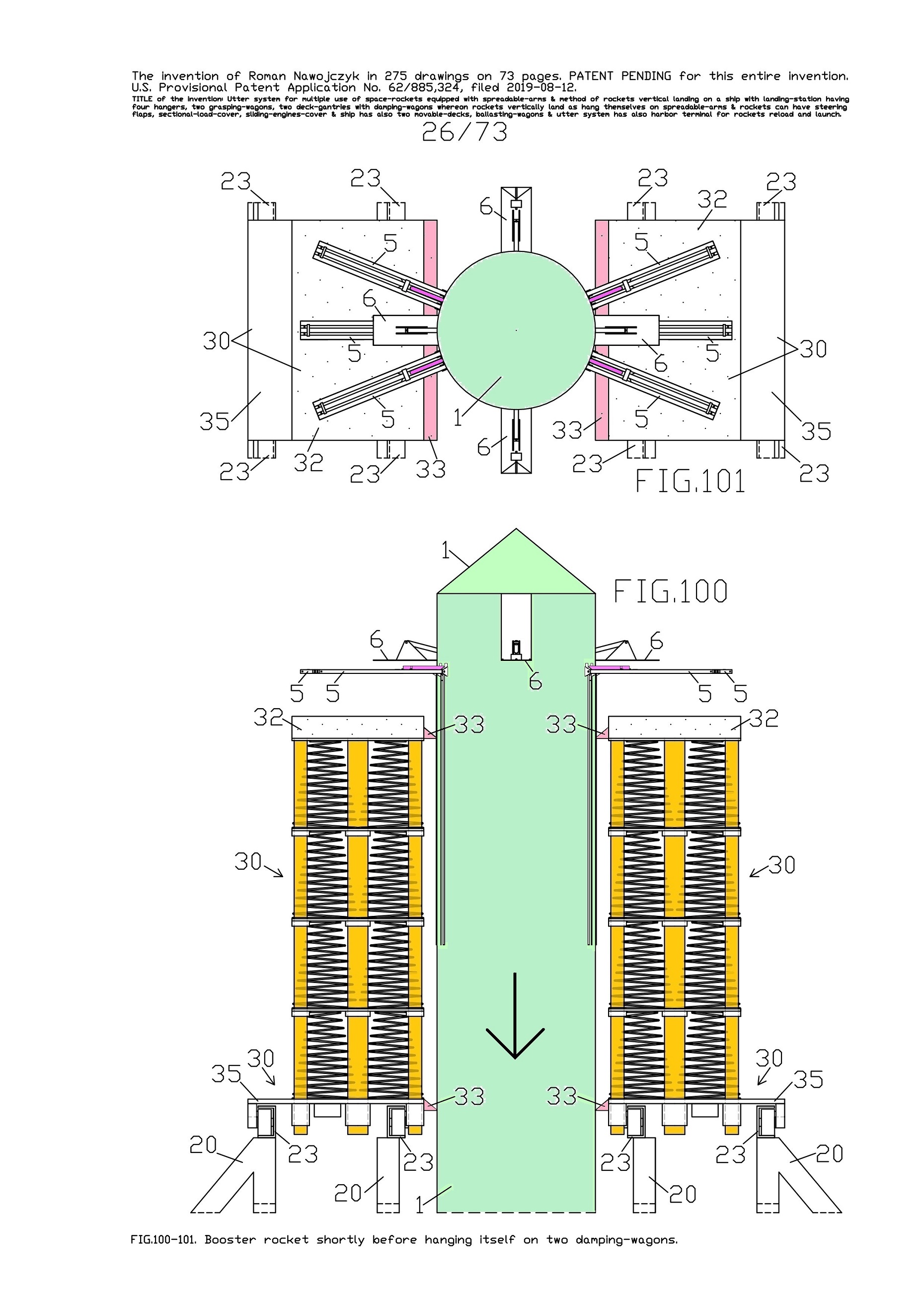
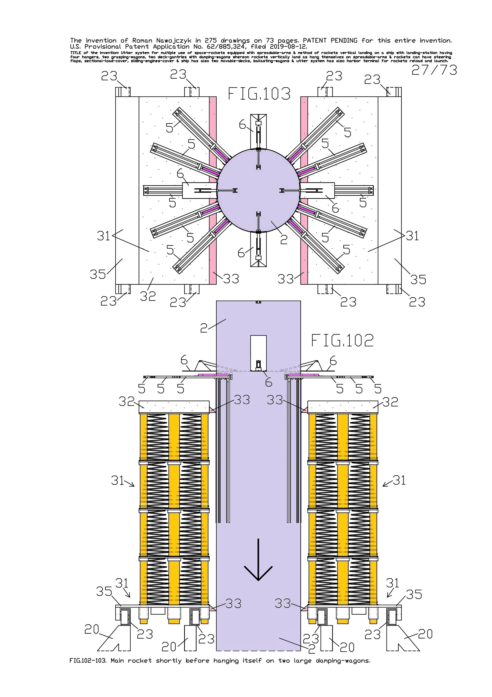
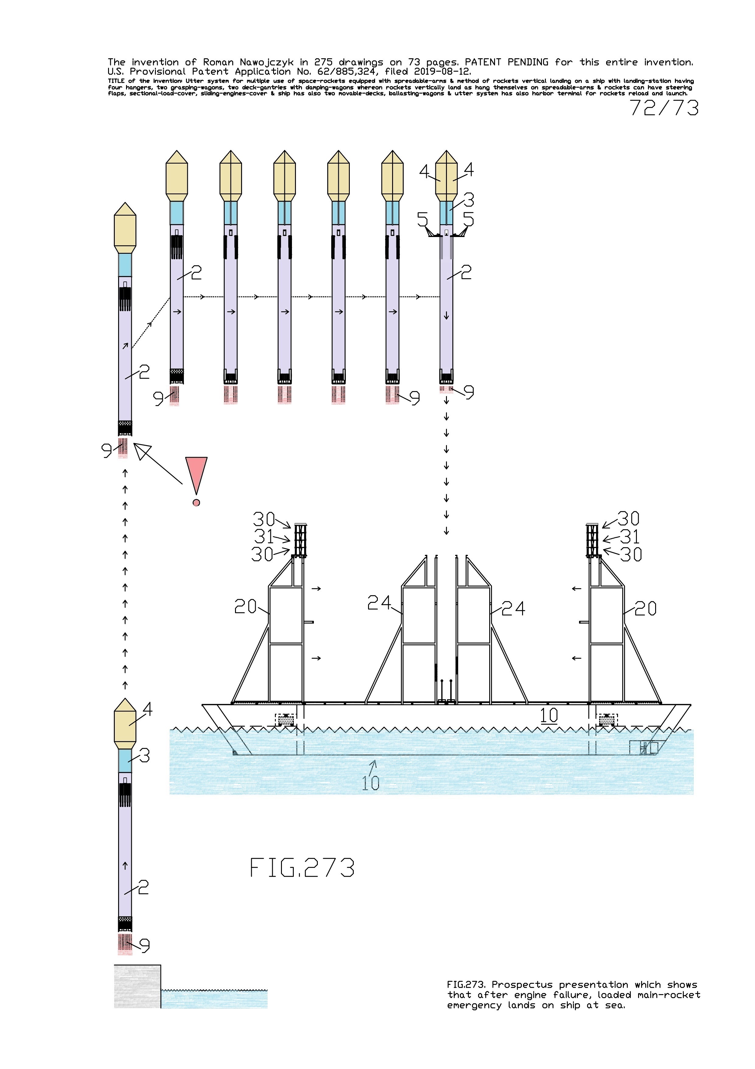
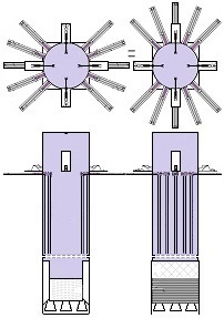
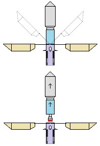
- allows multiple and quick reuse of the same space-rocket e.g., 2-3 times each day ! ! ! - allows that the space-rocket landing can sometimes occur together with attached modules e.g., second stage rocket and large return-load (e.g., satellite) ! ! ! Nowadays, not any company has such ability and not any planning it. In earlier times only Space Shuttles could accomplish suchlike tasks. - allows the space-rocket vertical landing on a sophisticated ship having landing station - allows the lift-off of three jointed space-rockets and later - - allows separated landing of these three space-rockets in a few minutes intervals on landing-station ! ! ! - causes that all space-rockets and their sub-assemblies and modules are designed and destined for multiple use thus return with rockets on Earth ! ! ! Hence, the space-rockets are totally reusable and NOT ANY garbage stay in space. - is perfectly suitable for the space-rocket launches with astronauts because the rocket landings are super safe ! ! ! - causes that the space-rocket lift-off from two ground-gantries is safer than the space-rocket lift-off in the usual manner.
The space-rocket lift-off from two ground-gantries creates also a few benefits like possibility of smooth igniting the main engines, smooth adjusting the rocket initial vertical position. The patent for this my entire invention is granted ! The patent has the number US 11 932 424 and is vissible on the US Patent and Trademark Office website. The alone patent in pdf. can be seen here
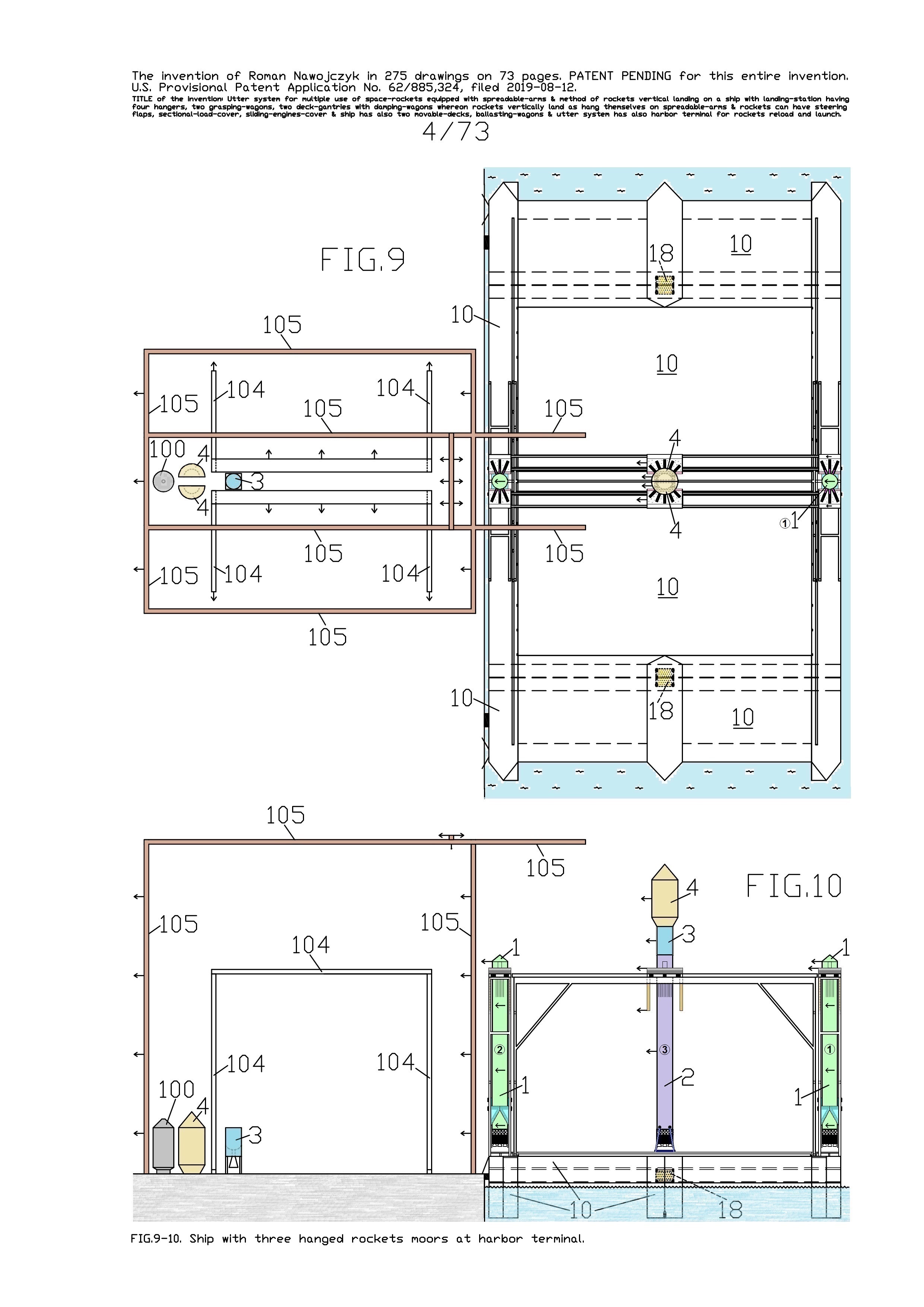
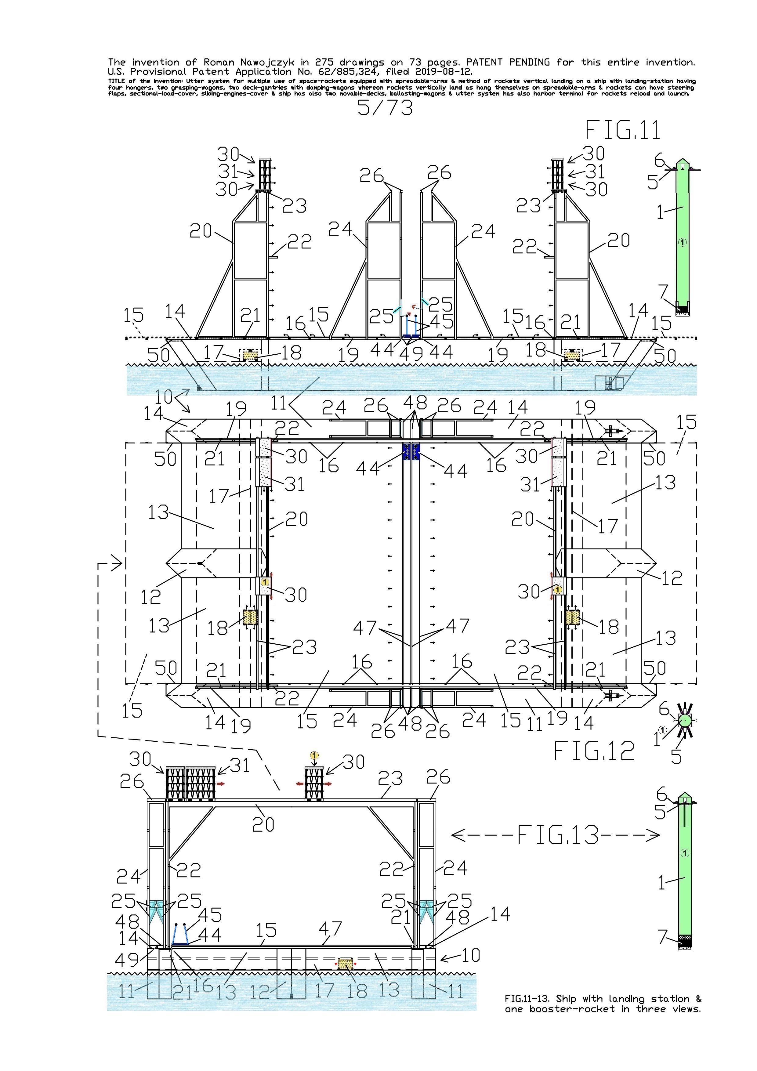
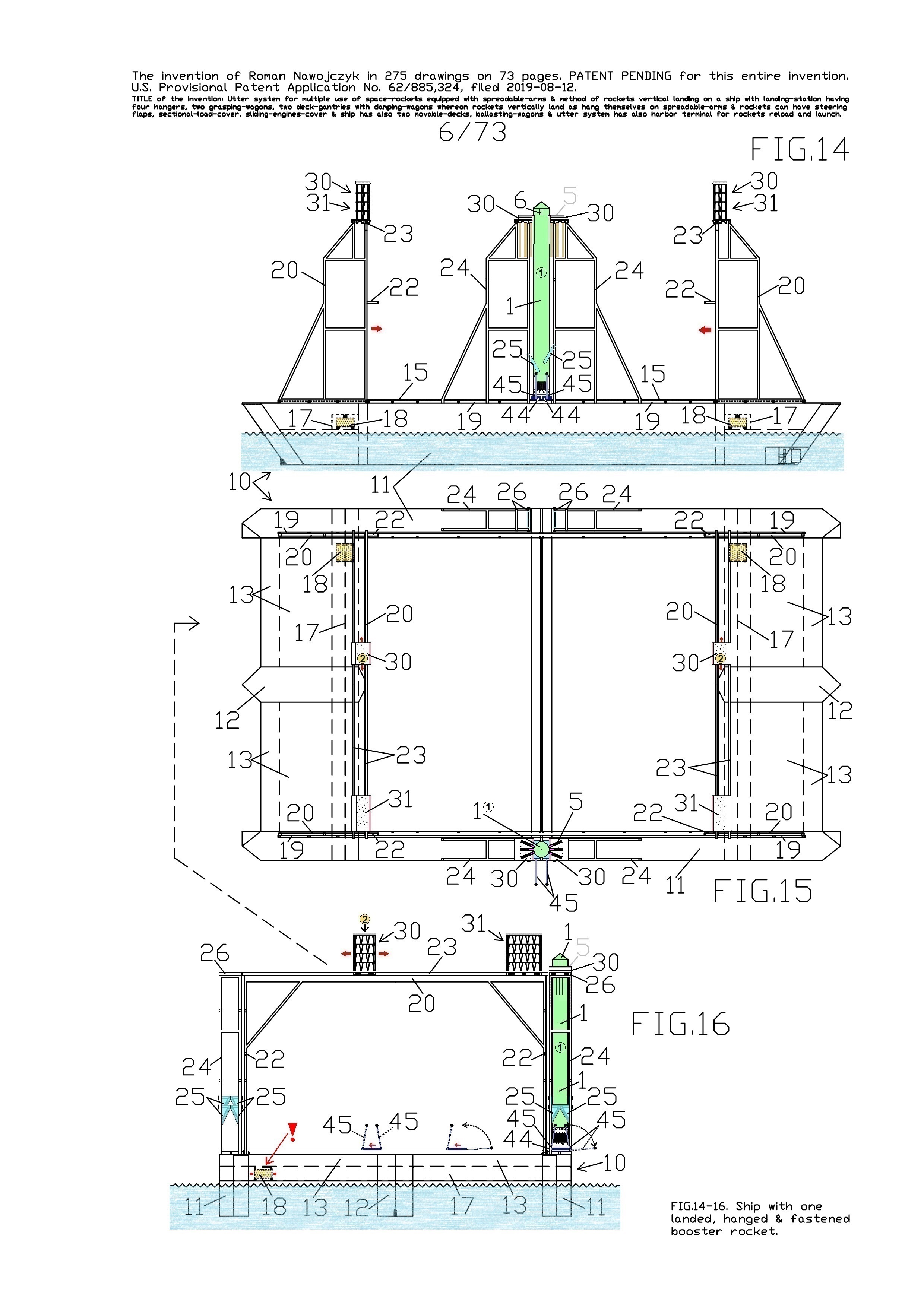
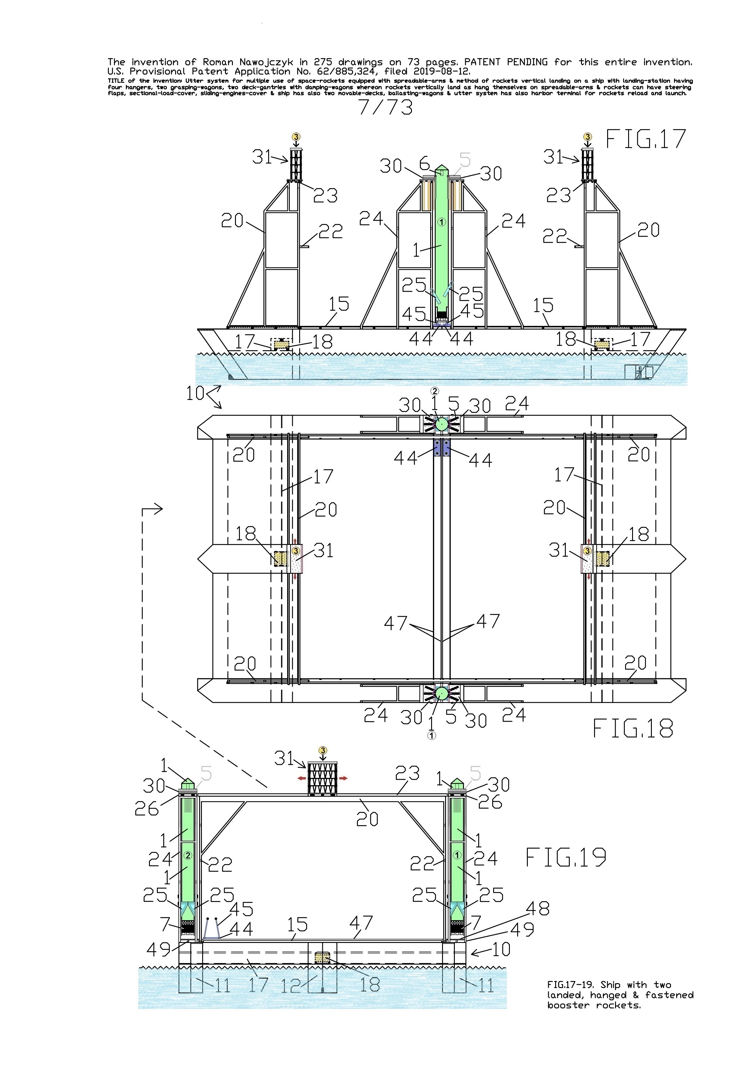
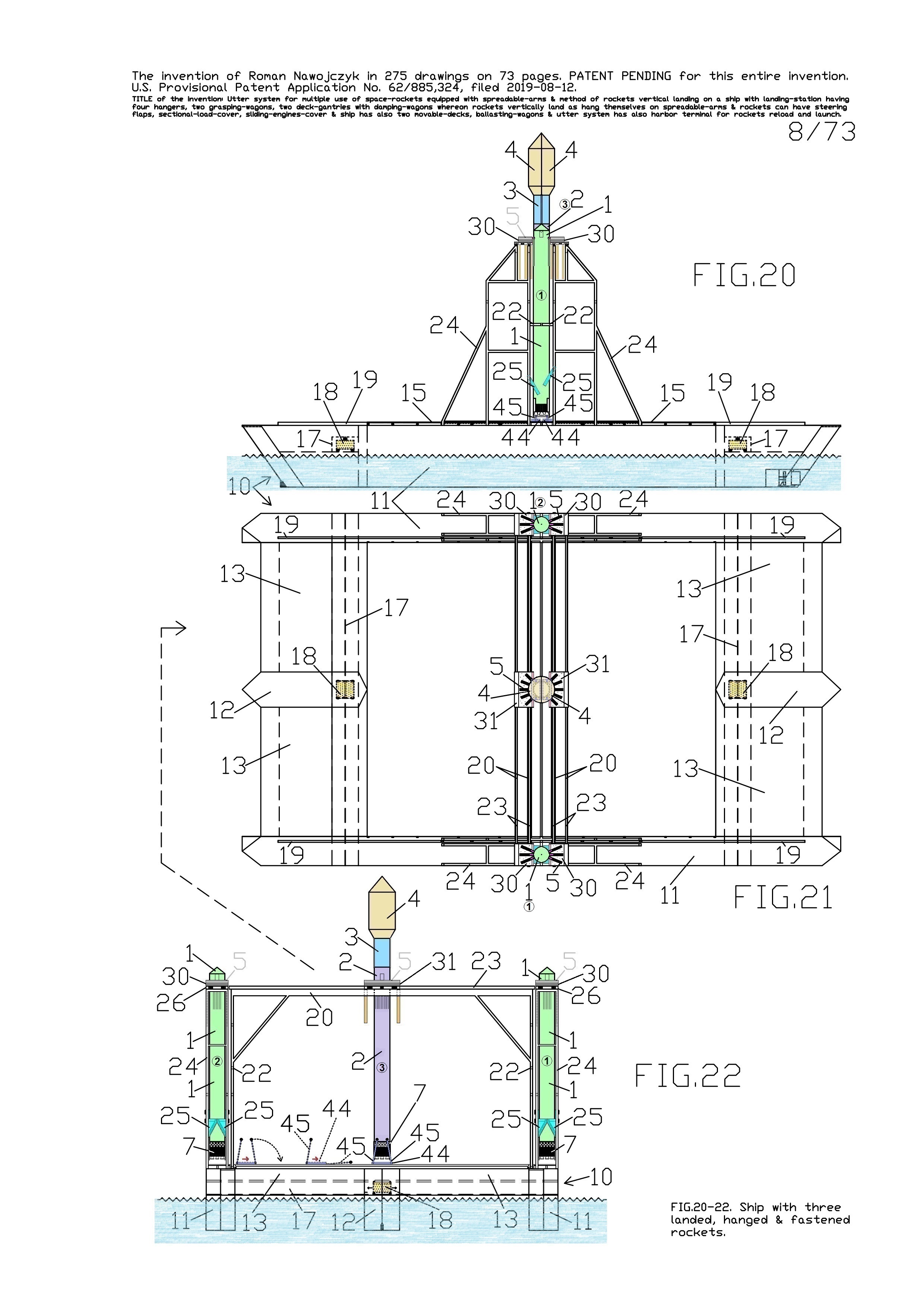
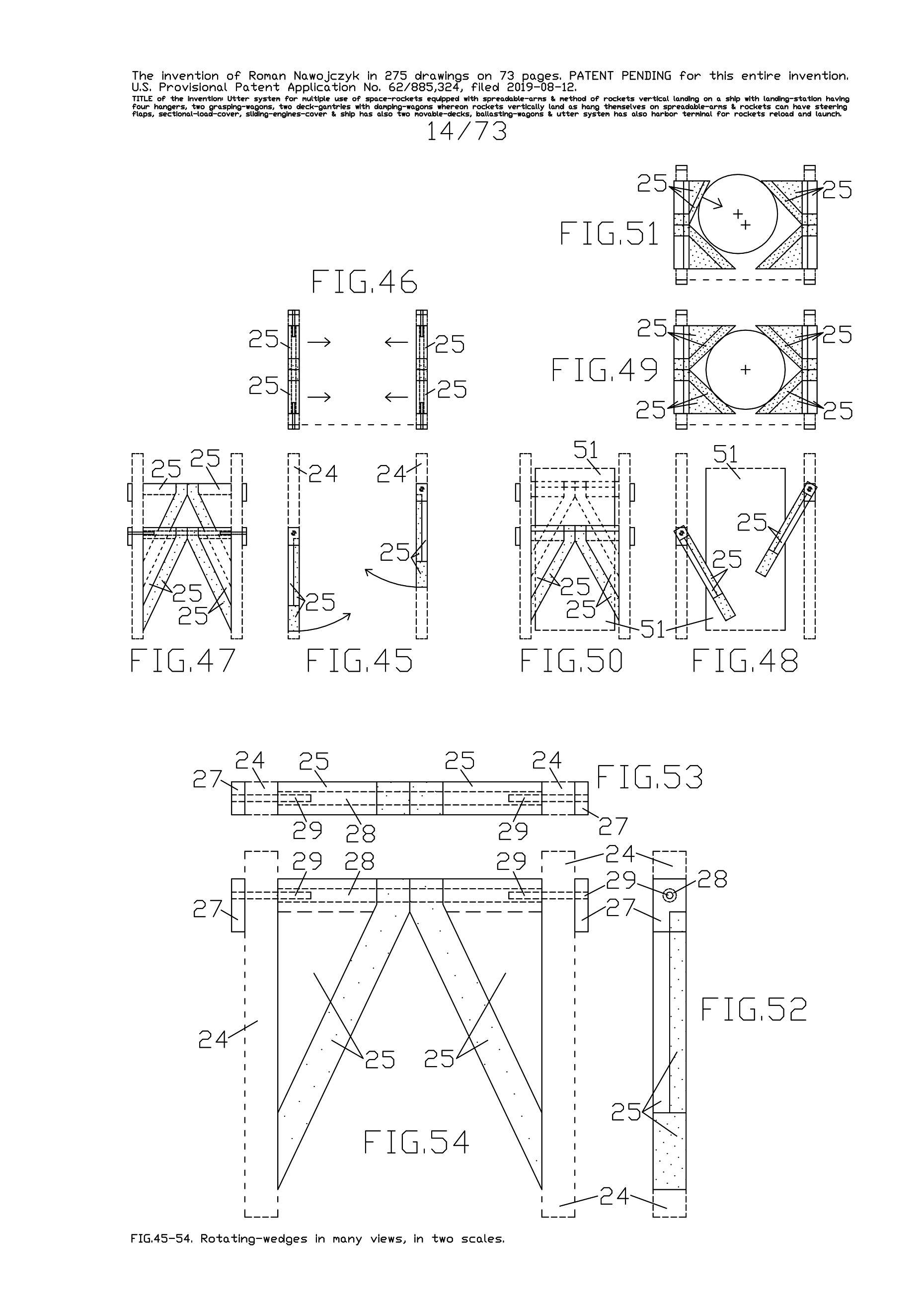
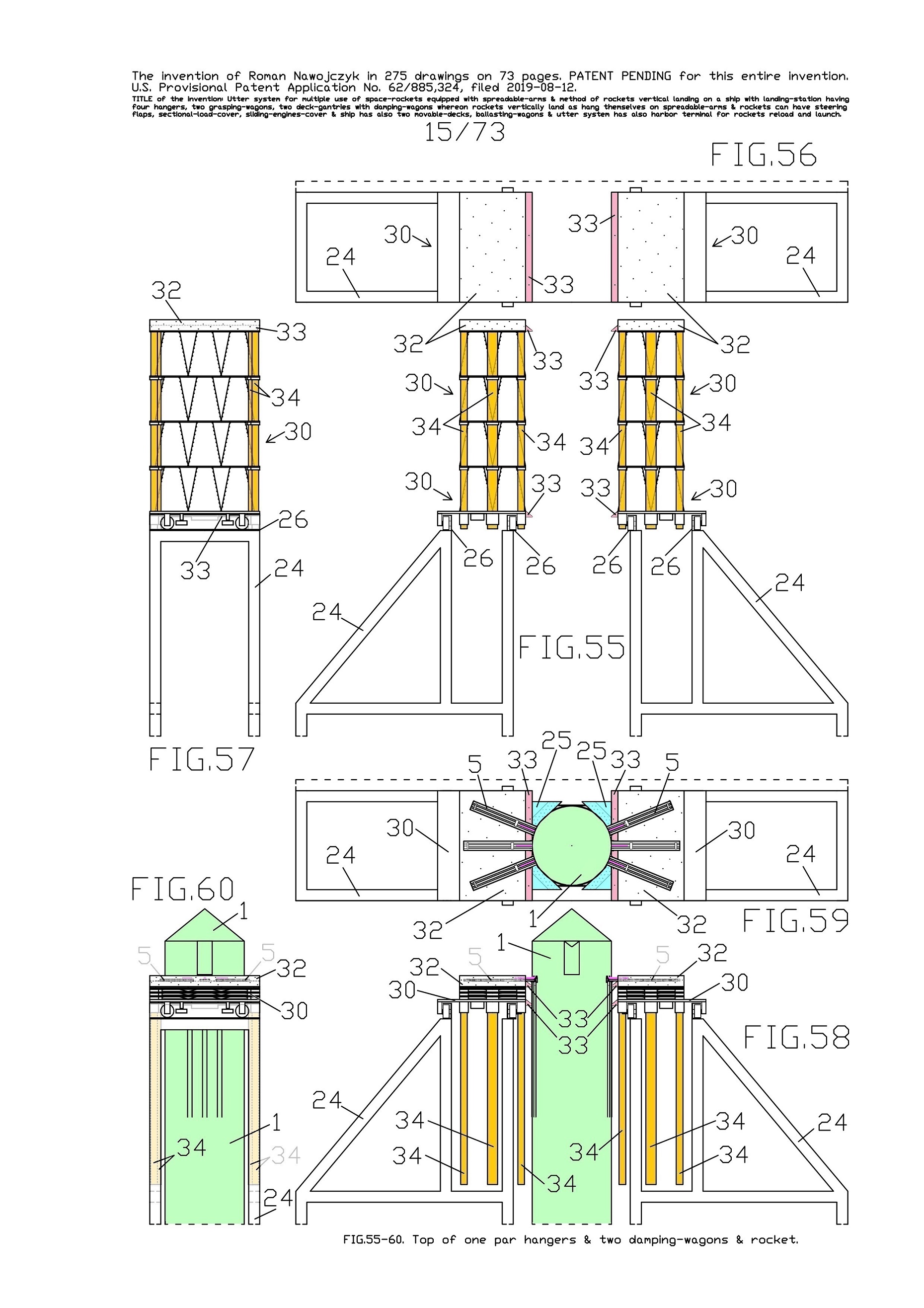
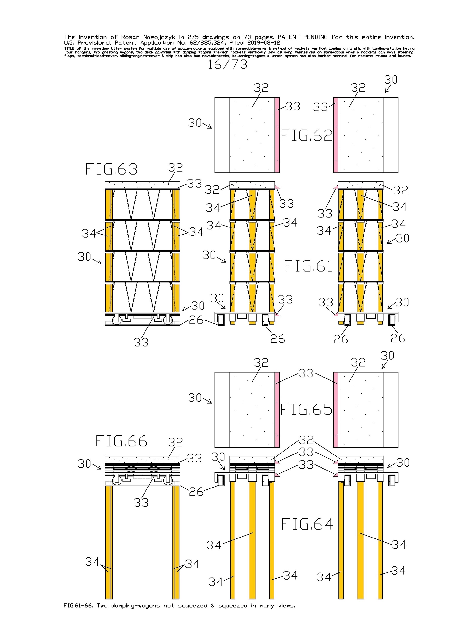
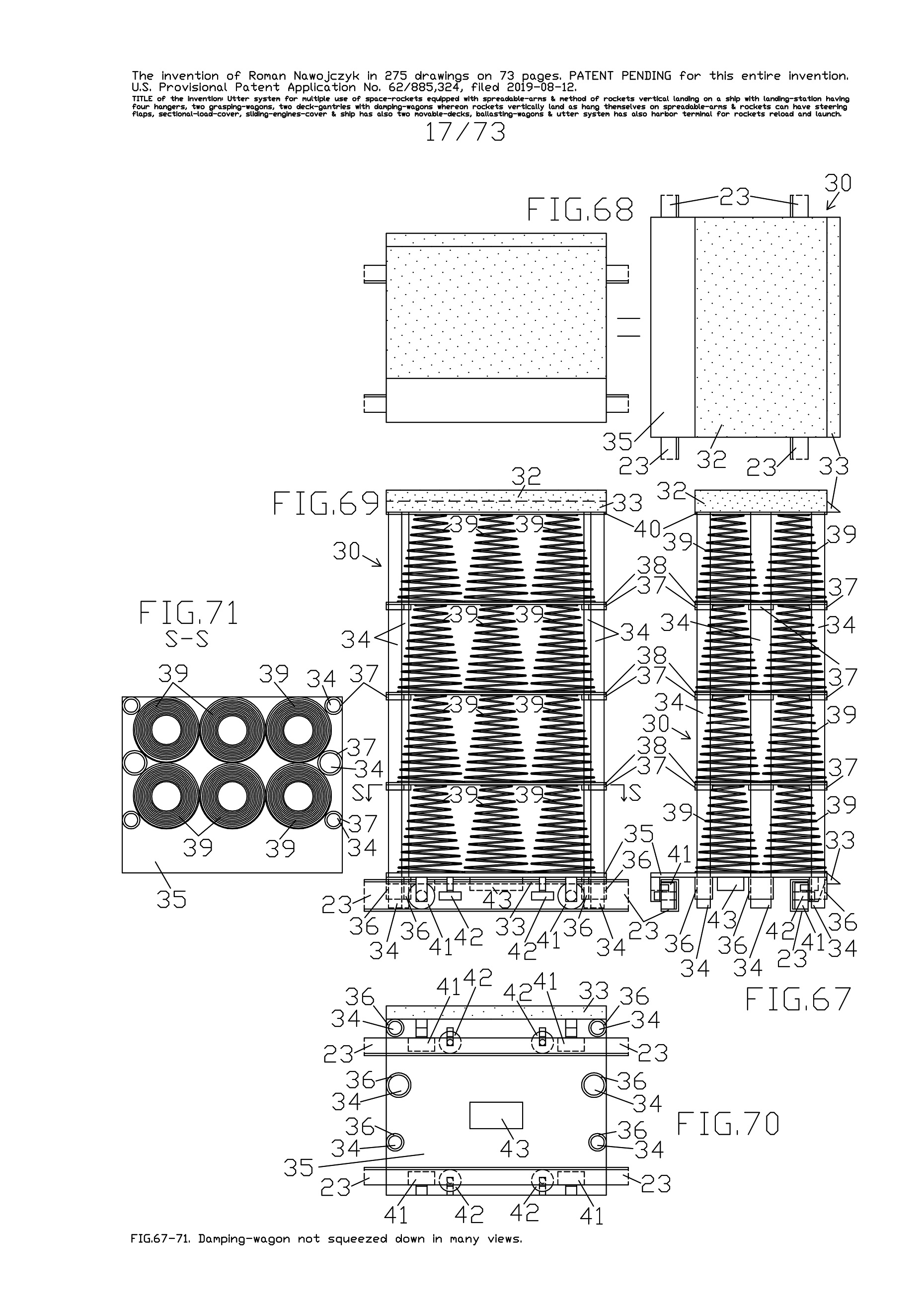
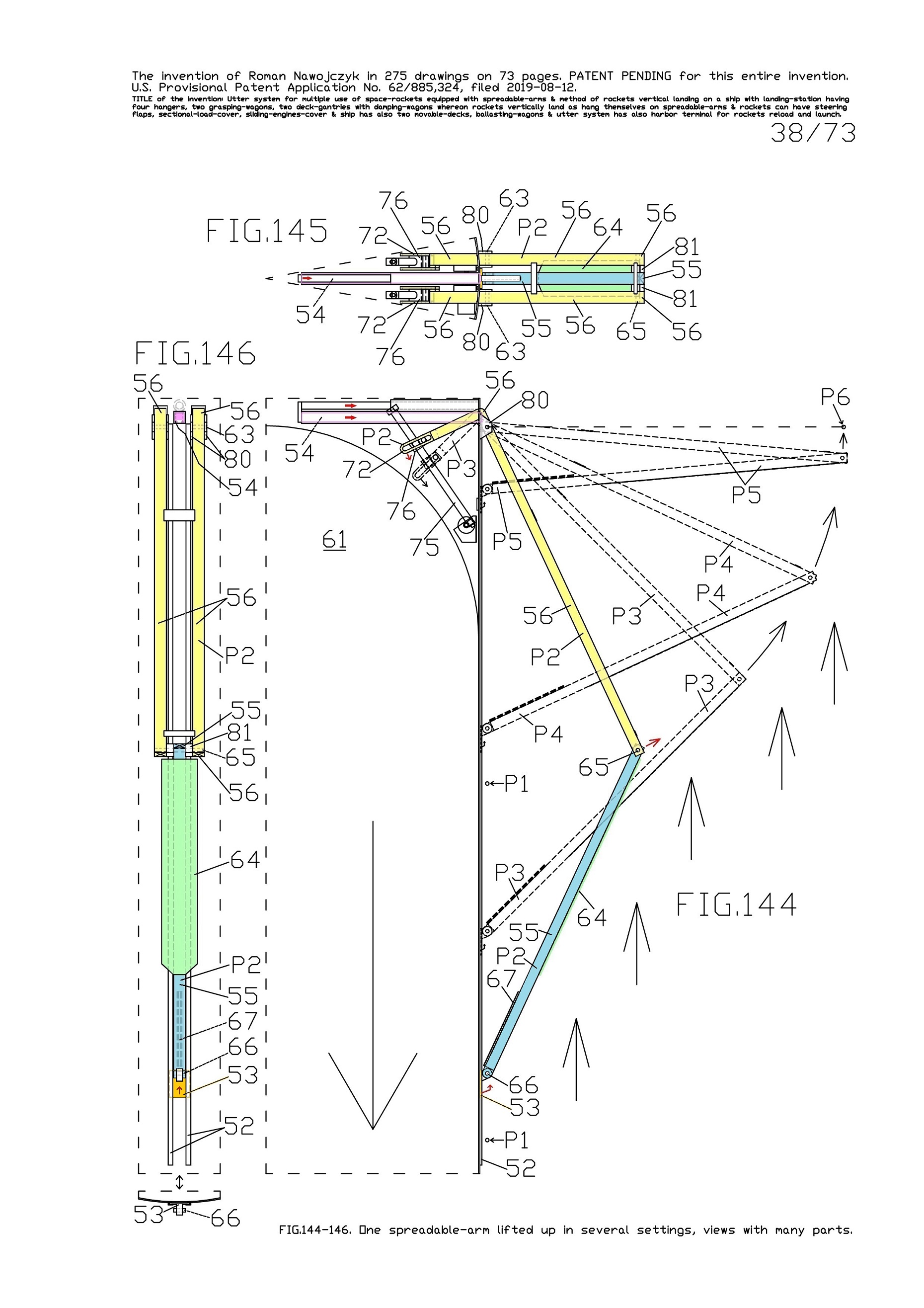
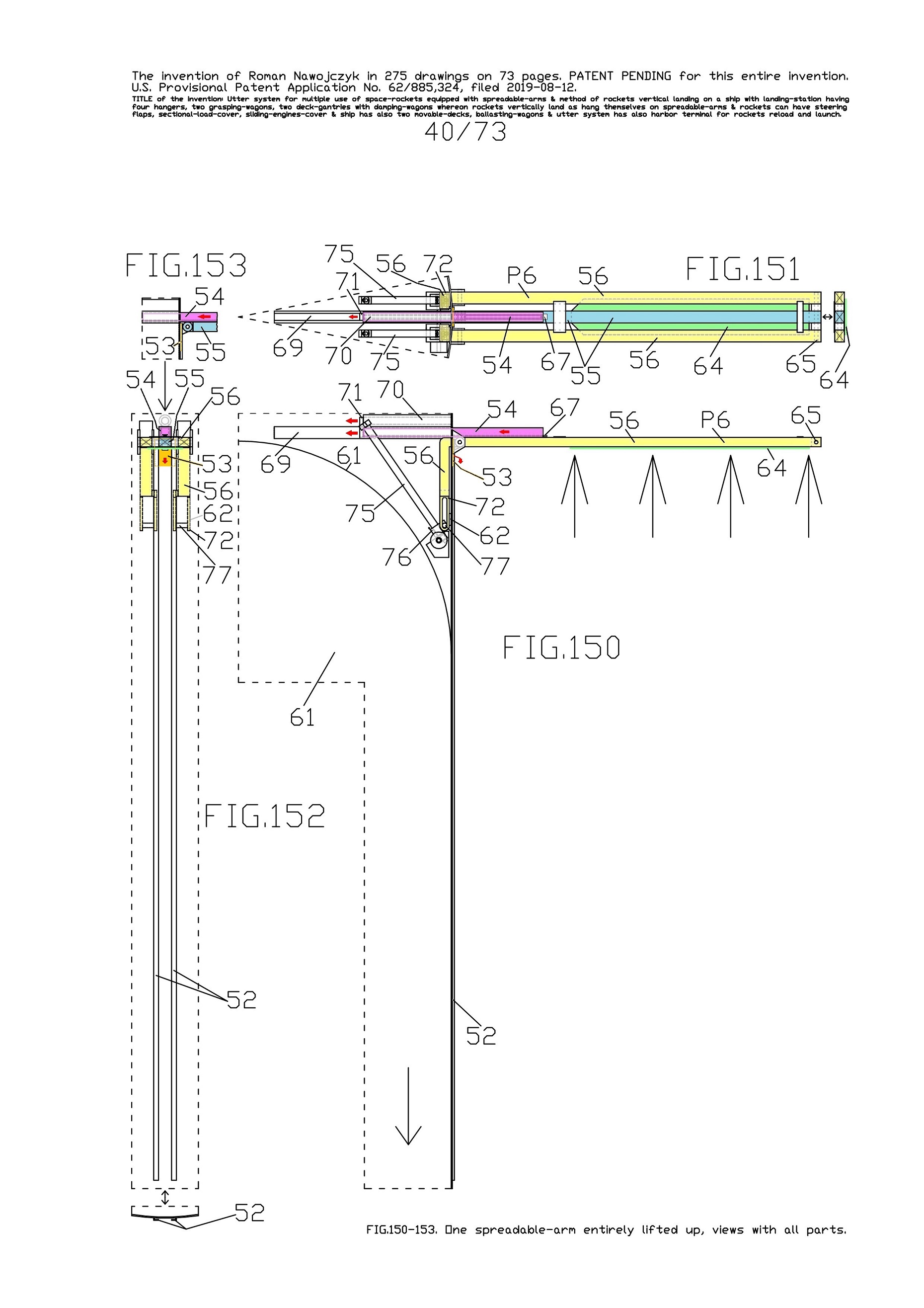
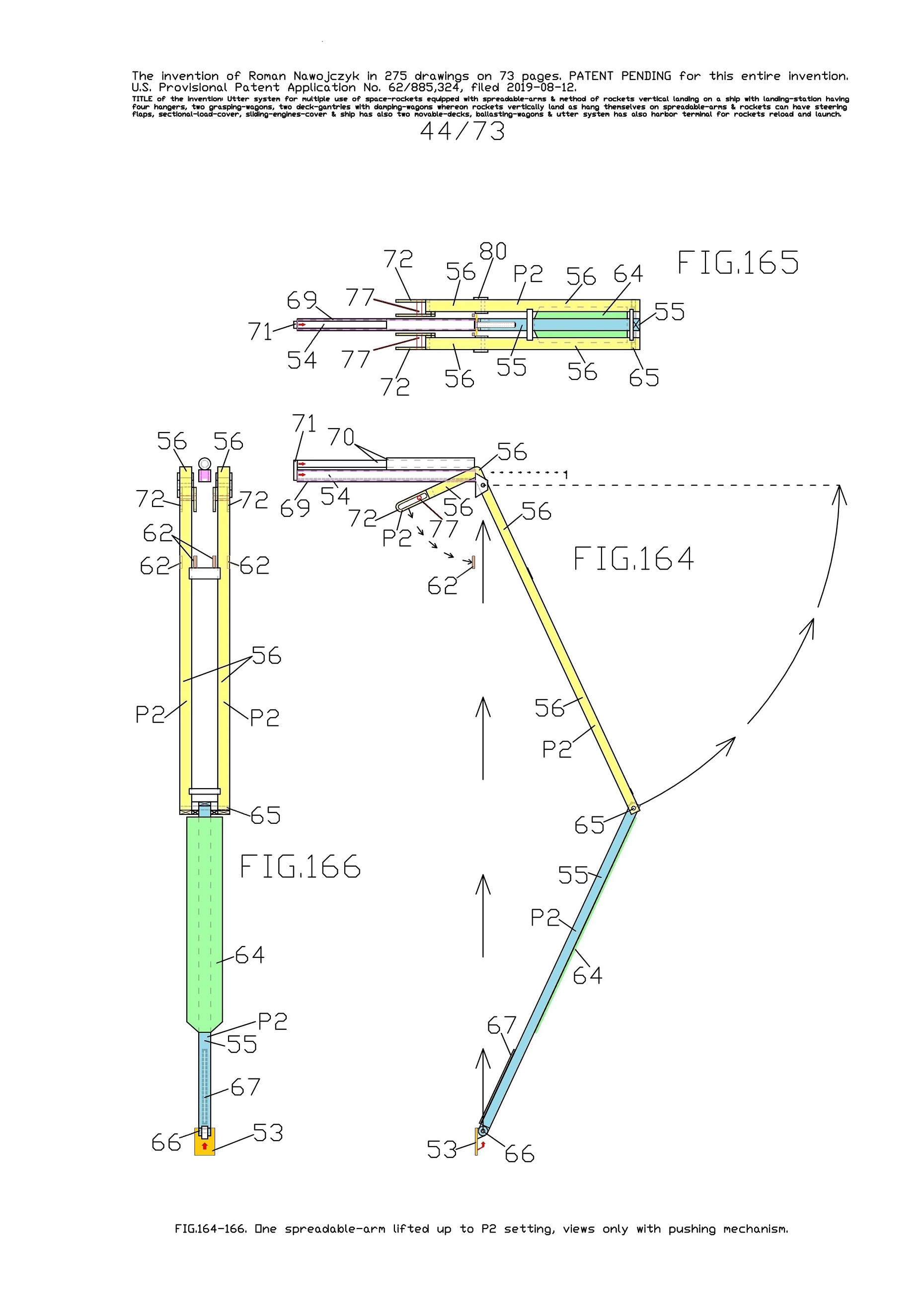
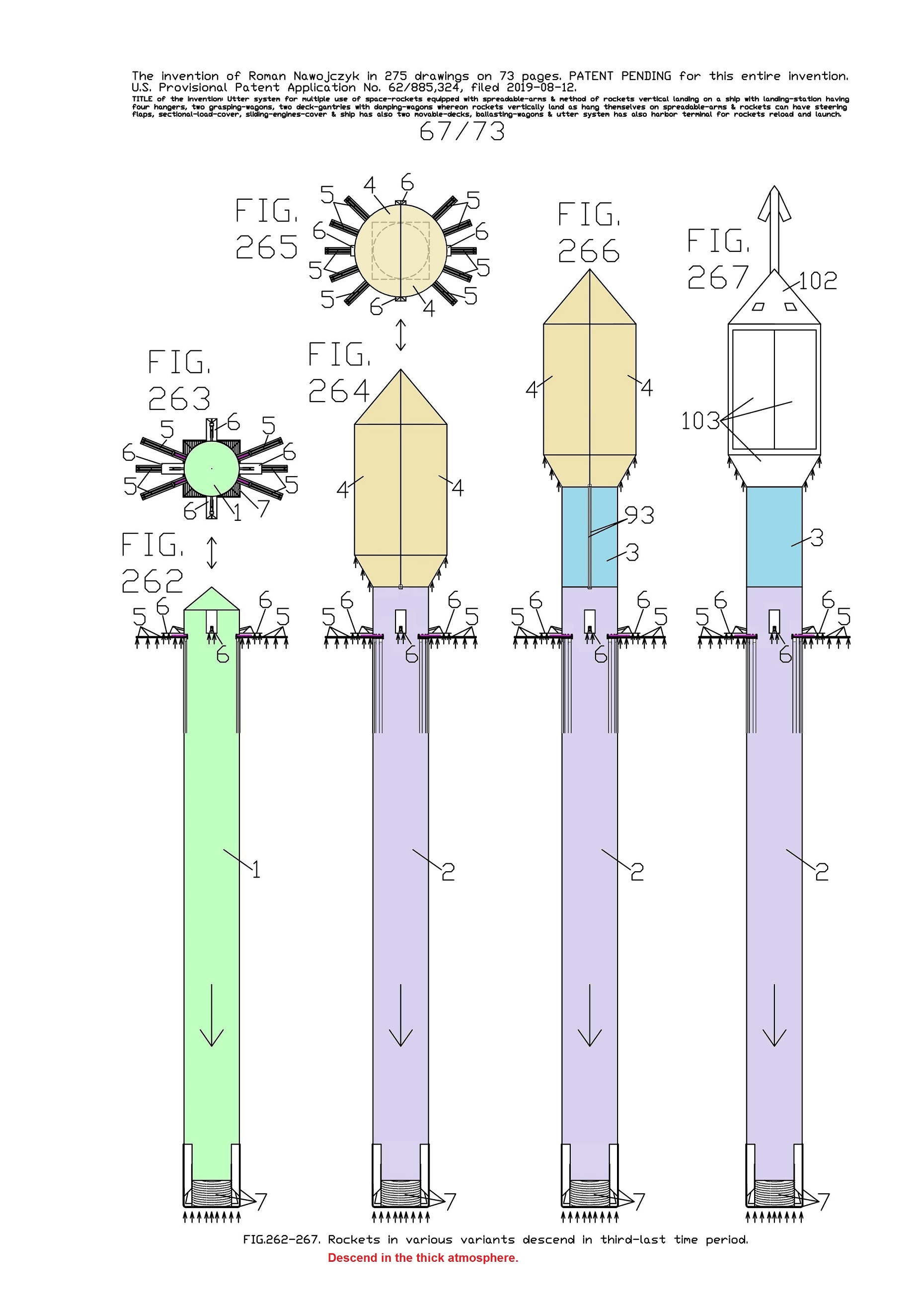
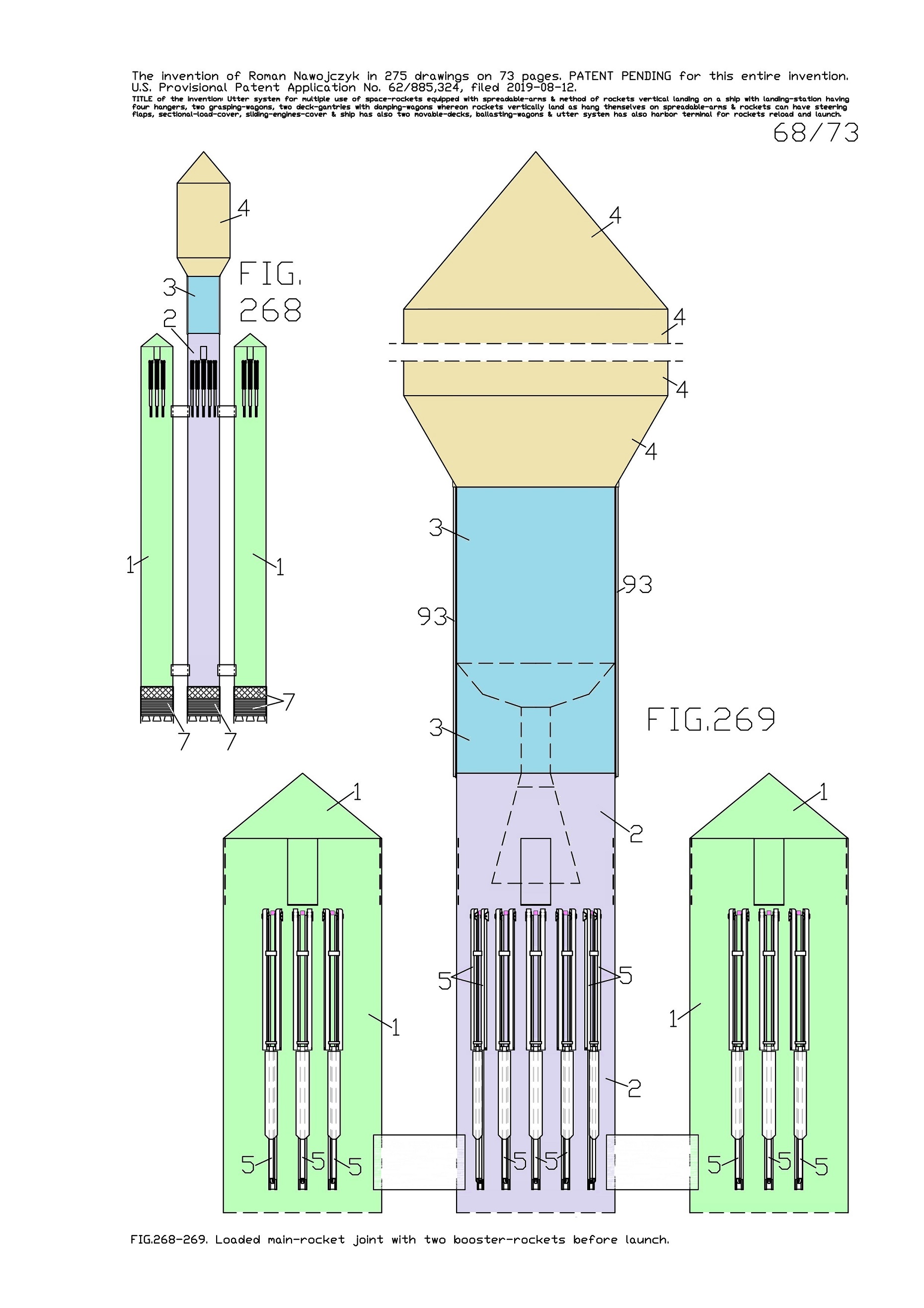
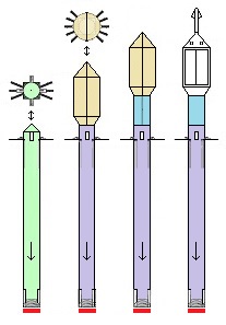
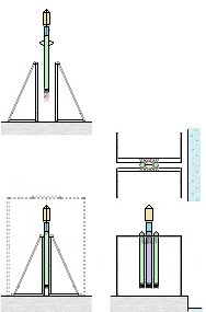
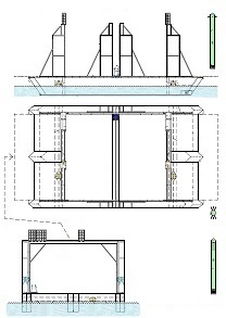
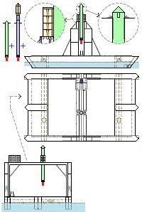
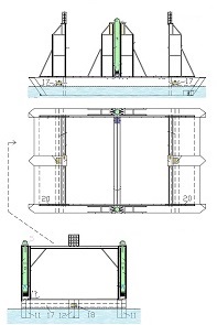
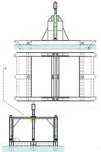
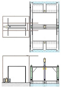
Earlier patent application for this invention was published 18 February 2021 by the US Patent and Trademark Office. The TITLE of my invention is Utter system for multiple use of the space-rockets equipped with spreadable-arms and possibly more devices, and method of these space-rockets vertical landing by hanging on landing-station having movable gantries and more apparatus. Rightful patent application was filed in the USA on 8 August 2020 and got the Class / Subclass: 244/002. My invention is depicted on 275 drawings ( 73 pages) which were done earlier in AutoCad and is described on 75 pages (37,700 words). You can see lots of drawings on this website. Below are some descriptions taken from my patent application and more other information. ABSTRACT of this INVENTION (like in the patent application) - System for multiple use of space rockets equipped with spreadable arms and sliding engines covers, and for said space rockets a vertical landing method on two movable gantries situated on a specific sea ship or on a solid ground. Said space rockets comprise steering flaps and a dividable sectional load cover. The specific sea ship comprises specific joined hulls, two horizontally movable decks and tunnels with ballasting wagons. The specific sea ship has installed a landing station for the space rockets. The landing station comprises hangers, grasping wagons and two movable ship gantries. The hangers comprise rotating wedges. The gantries comprise damping wagons. The system comprises also two movable ground gantries and a specific movable ground crane all situated on a solid ground that together create a multi-task station for the space rockets hanging up, reloading, launching, and landing. The system allows that the space rockets can liftoff from two movable gantries while vertically hang on their spreadable arms. SUMMARY of this INVENTION (like in the patent application) - The movable gantries are in two versions, as two movable ship gantries and as two movable ground gantries. Two movable ship gantries are installed in a landing station, which is mounted on a specific sea ship deck. Both movable ground gantries are installed in a multi-task station situated on a solid ground. The landing station has two movable ship gantries and two pairs of hangers for two space rockets. Both movable ship gantries are huge and are installed over the central part of the specific sea ship. Both movable ship gantries at the chassis bottom have a plurality of driving wheels to precisely roll on the specific sea ship decks length-ways. Both movable ship gantries have on a chassis top two rails each with installed a plurality of damping wagons whereon the space rockets vertically land as hang themselves on their spreadable arms. Furthermore, on the specific sea ship movable decks two grasping wagons help secure the space rockets at their bottoms. Both grasping wagons are installed on the specific sea ship two horizontally movable decks. On the current deck mounted landing station in a few minutes intervals can land three space rockets equipped with the spreadable arms. Two first landing space rockets can be quickly moved on two pairs of hangers and temporary fasten. That is because one pair of hangers is adapted for hanging one space rocket equipped with the spreadable arms and temporary fastening said space rocket at the bottom by means of four rotating wedges. The third landed space rocket can remain on both movable ship gantries and be fastened by both grasping wagons. The multi-task station has two movable ground gantries and a movable specific ground crane. This entire system is completely connected with utilization of the plurality of spreadable arms mounted on all space rockets. Therefor these spreadable arms are the main characteristic feature of this system. Furthermore, each space rocket vertical landing can occur with attached a plurality of modules and possibly a return load, and this feature is very important possibility and advantage of this system. Therefor this system includes that all space rockets and their sub-assemblies and modules are designed and destined for multiple use thus, return with the space rockets on the Earth. Moreover, this whole system comprises also the multi-task station, which is adapted for hanging up, reload, launch preparation, lift-off and vertical landing of the space rockets equipped with the spreadable arms. And that includes also unloading the space rockets from the specific sea ship. The multi-task station has two movable ground gantries and one movable specific ground crane. Therefor this system includes also that a plurality of jointed space rockets during hanging on two movable ground gantries can be launch prepared in vertical position thus, while they vertically hang on their spreadable arms. And then these three jointed space rockets can lift-off from these two movable ground gantries thus, while they vertically hang on their spreadable arms as well. Each spreadable arm consists of two lateral beams, one middle beam and additional sub-assemblies. Over each spreadable arm moving mechanism is installed a pushing mechanism having a blocking bar, which serves for blocking the middle beam in the spreadable arm, while it is entirely lifted. The blocking bar fulfills blocking function when is maximally slid outside the fuselage. In such state, the blocking bar fulfills its main function, which is total blocking the middle beam in all directions. The middle beam after its blocking gains possibility of carrying burdens in all directions. On this landing station in a few minutes intervals can land three space rockets equipped with the spreadable arms. Two first landing space rockets can be quickly moved on two pairs of hangers and temporary fasten. Because each one pair of hangers is adapted for hanging one space rocket equipped with the spreadable arms and temporary fastening said space rocket at the bottom by means of four rotating wedges. The third landed space rocket remains on both movable ship gantries and is fastened by means of four raised rotating poles, which reach from two grasping wagons. Presented here, the specific sea ship with landing station having strong temporary fastening of the space rockets enables sea-transportation even at stormy sea. Both movable ship gantries are huge and are installed over the central part of the specific sea ship. Both movable ship gantries can precisely and separably roll along the entire specific sea ship. Before landing of every space rocket, both movable ship gantries are entirely spread apart in two opposite directions of this specific sea ship. In such arrangement both movable ship gantries are ready and await landing of every space rocket. Both movable ship gantries can approach to each over and touch on themselves by means of two bumpers. Therefor short time before landing of each space rocket, both movable ship gantries approach to each over and together place themselves under the landing space rocket. In order to accomplish it, each movable ship gantry can roll until direction of the opposite movable ship gantry, if necessary during landing of the space rocket. It causes that each space rocket can land almost on the entire length of the specific sea ship. While, on the drawings there are shown only landings examples in the specific sea ship center. Each damping wagon has four layers of a plurality of conic springs in vertical setting, which can be in fullness compressed. Therefor all damping wagons have damping high range during hanging the space rockets equipped with the spreadable arms. Simultaneously all damping wagons maintain unshaken and stable top surfaces during their compressing by the space rocket. Moreover, both grasping wagons can together roll on rails between one pair of hangers. Because both grasping wagons are low build and are situated on both horizontally movable decks, they can move under every space rocket, which will hang itself on two damping wagons on both movable ship gantries. After each space rocket landing, both grasping wagons will move under this space rocket bottom and will suppress its swinging bottom by means of four raised rotating poles. Afterward two compressed damping wagons with hanged space rocket and both grasping wagons having grasped this space rocket bottom, as a complete set can move to one side of the specific sea ship Both movable ground gantries at the chassis bottom have installed a plurality of driving wheels to precisely drive on the solid ground and turn on it. Both movable ground gantries on their tops have fastened the rails for possible installing the damping wagons. Both movable ground gantries are adapted to approach to each over before landing of the space rocket. Both movable ground gantries are adapted to place themselves precisely under landing space rocket equipped with the spreadable arms. The movable specific ground crane is a lot bigger than both movable ground gantries. The movable specific ground crane is adapted to play along with both movable ground gantries. The movable specific ground crane has a plurality of beams, which reach up over the specific sea ship so that this movable specific ground crane could lift one space rocket and subsequently shift it on both movable ground gantries. The entire movable specific ground crane will move backwards before the space rocket lift-off. Both movable ground gantries serve for three space rockets lading after unloading from the specific sea ship. And later these two movable ground gantries serve for three joined space rockets launch preparation all time in vertical position thus, during hanging on these two movable ground gantries. And therefor all space rockets can lift-off from two movable ground gantries while these space rockets vertically hang on their spreadable arms. This even includes that three joined space rockets can lift-off this way. Both movable ground gantries will spread apart on two sides immediately after the space rockets lift-off. Summing-up, as result of this whole system with method of the space rockets launches and their quick return to the multi-task station there is possible their very fast renewed launch, for example several hours after landing on the specific sea ship. |
|
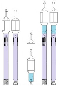
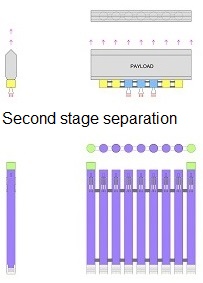
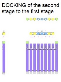
Here, I want to show up unbelievable possibility of this System. It is possibility of launching the huge in dimension payloads and with the huge weight e.g., 500 metric tons. It seems unbelievable, however it is shown on drawings. It is possible by composing a huge assemblage of several permanently joined space-rockets in the row. Those all joined first stage rockets will not separate from each other during launch, staying in space for docking back the second stage and landing together with it. Hence, such huge assemblage of several permanently joined space-rockets in the row will hang on their all spreadable-arms before launch. Next all space-rockets will lift-off together and later will land together on their all spreadable-arms. Suchlike huge assemblages of permanently joined space-rockets in the row were not possible before.
LICENSING_of_UTTER_SYSTEM. With this website, I offer this invention for licensing. For this System, I already designed lots of improvements, upgrades and refinements which would make it even more developed and perfect. They will be available together with a purchase of licence. INVESTORS are welcome with some propositions. DONATIONS or SPONSORING. and about me. Below are shown 50 pages with the drawings from my patent application. For the large drawings click on drawings. These pages are in 100% and 75% picture resolutions. Click here for the same pages in 40% picture resolutions with descriptions.
REFERENCE NUMBERS of this invention. The INFORMATION which was NOT INCLUDED in my patent application. TECHNICAL FIELD of this INVENTION (like in the patent application). The present invention and its disclosure is directed generally to some space-rockets overall applying and usage, and their associated systems and methods. BACKGROUND of this INVENTION (like in the patent application).
Since long time ago the space rockets are applied and used. Nonetheless, to this day one did not invent some system of space rocket launching and landing, which altogether would recover it, and would be very reliable, secure, trouble-free to use. And simultaneously the system that would enable the same space rocket launch several hours after its landing. Nowadays, particularly the space rocket landing is very problematic. Currently, a few companies land the space rocket first stages on varied spreadable legs but such landings has several disadvantages. For example, during landing, the space rocket legs can be spread out only a few seconds before touch-down, because only then the space rocket descent is at low speed. Otherwise, atmospheric air would too strongly push the legs upward. Landing on the legs is very uncertain and sometimes after touch-down the space rocket can fall over by lots of reasons. In the event of one leg failure the whole space rocket will surely fall over. Landing on the legs makes it difficult to utilize some damping mechanisms in the legs because they would possibly cause the space rocket fall over as well. While, on the other hand a lack of some damping mechanisms in the legs can cause their breakdown. Sometimes after landing on the legs, the space rocket stands slanted and can suddenly fall over as well. Therefore, the slanted space-rocket will not securely stand on the legs. Such situation is very problematic and danger for all working personnel. During landing on the legs, the space rocket legs are spread around plenty white-hot flames exhausting from the main engines. During touch-down these flames also rebound from the landing pad toward the legs thus, during this time they are burnt and destroyed in some part. Consequently, the legs have to stand on the landing pad, which is in plenty white-hot flames. Landing on the legs makes impossible an application of very tall space-rockets, or that these space rockets would have mounted on their tops some modules or loads. Landings on the legs require almost windless weather conditions because even moderate wind can cause the space rockets fall over and thus their total loss. As result, comes conclusion that at windy conditions the space rockets can not lift-off because later they will not be able to land on the legs. And it further causes that sometimes the space rockets having legs must wait several days for a launch possibility. There would not be such problems when landings would take place on presented in this invention spreadable arms. The spreadable legs installed in a space rocket fuselage bottom makes it difficult for installing there some foldable thermal cover of main engines, as it is presented in current invention. Therefore, currently, landings on the space rockets legs have characteristic of continuous attempts and hence all landings are treated as secondary purposes of all space rockets launching. Whereas, plenty other companies do not endeavor the space rocket landings at all. Furthermore, for security reasons it is recommended so that all space rockets landings would take place on the sea ships at sea. And for this reason landing on the space rocket legs and on a rolling sea ships are worse uncertain. Earlier were applied Space Shuttles, which had plenty advantages, rather secure landing although unsafe lift-off. However, the Space Shuttles had very large and heavy wings and furthermore, several heavy wheels with heavy suspension. The large wings extorted usage of a complex and heavy thermal cover of the whole Space Shuttle. As a result of mentioned disadvantages and high operating costs the Space Shuttles one withdrew from the use. All-in, currently, all over the world there are not possibilities of returns and regains from an Earth's orbit entire space rockets or entire loads. Yet, there are applied small capsules, which return from the Earth's orbit and land using the parachutes. This is a very primitive solution. Presented here invention does not have all before mentioned disadvantages. |
| THE END |